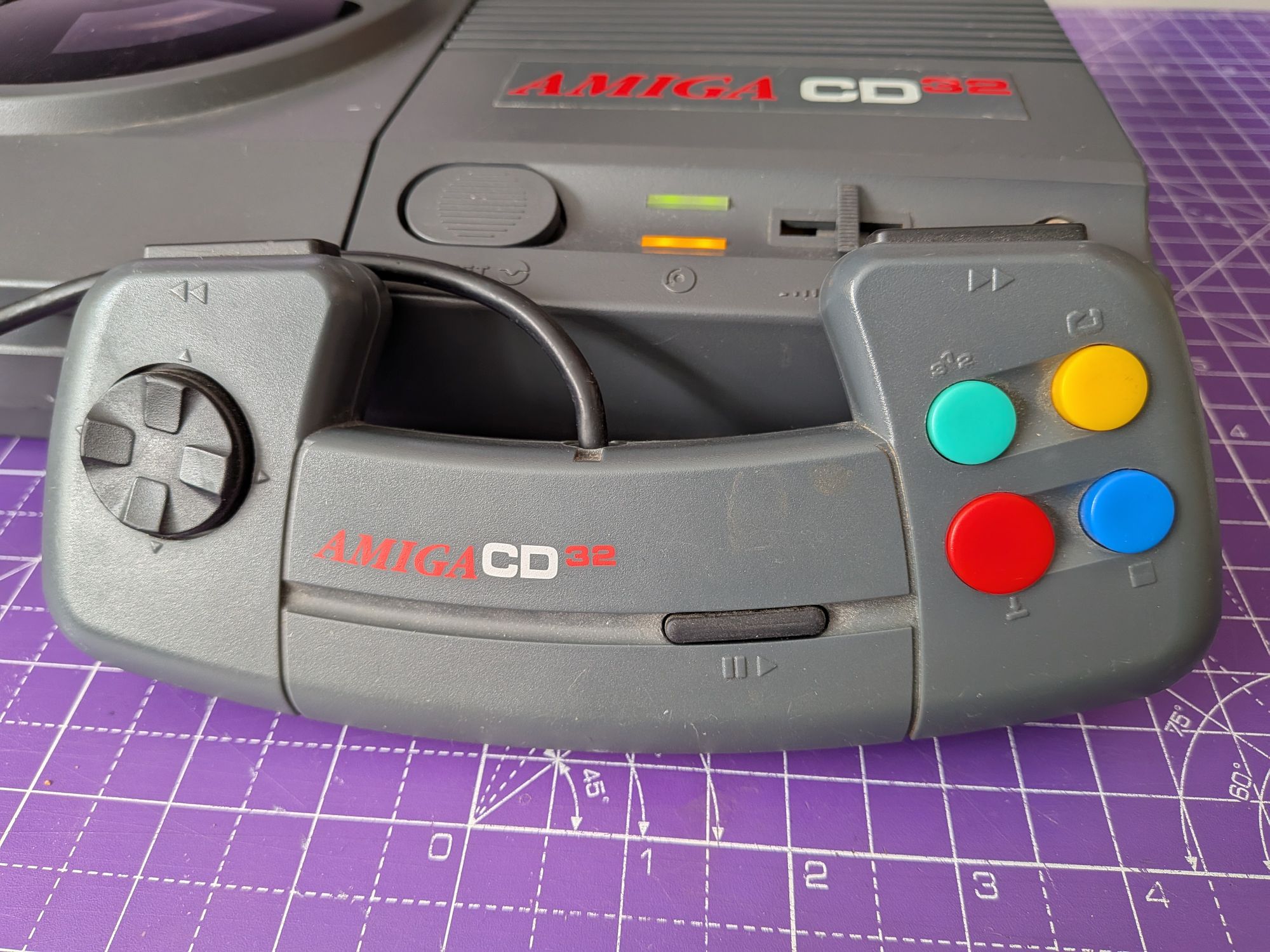


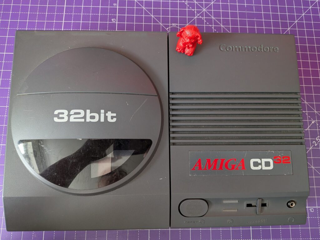
A 32 bit CD based consolised Amiga based games system.
These are quite sought after now, and a lovely thing it is too. A great example here in really well looked after condition, in for some slightly overdue maintenance. It’s a childhood system which has been with its owner since new. That makes it special, doesn’t it. I still have the 8 bit micro I grew up with. It holds a lot of memories, most of them good.
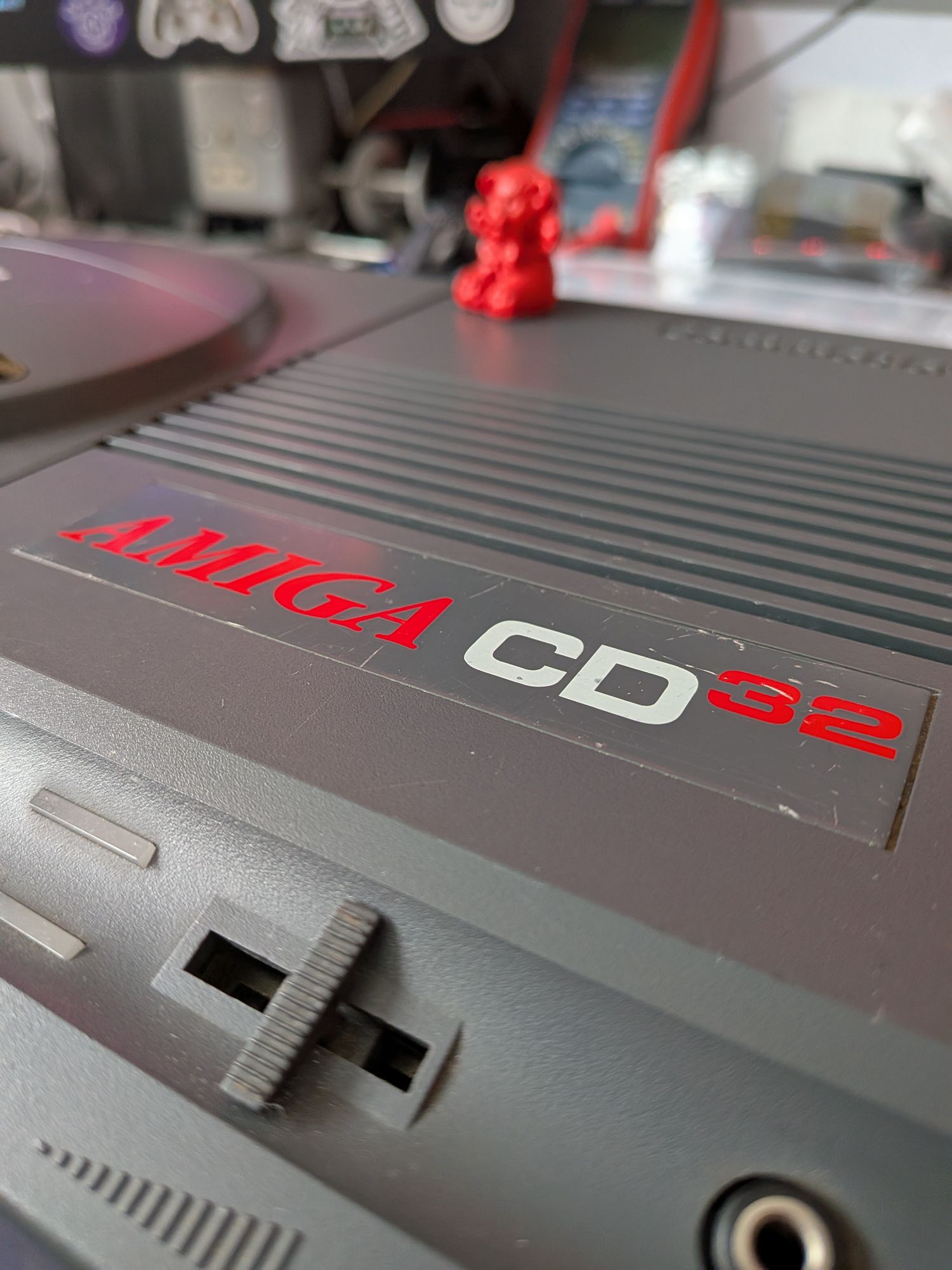
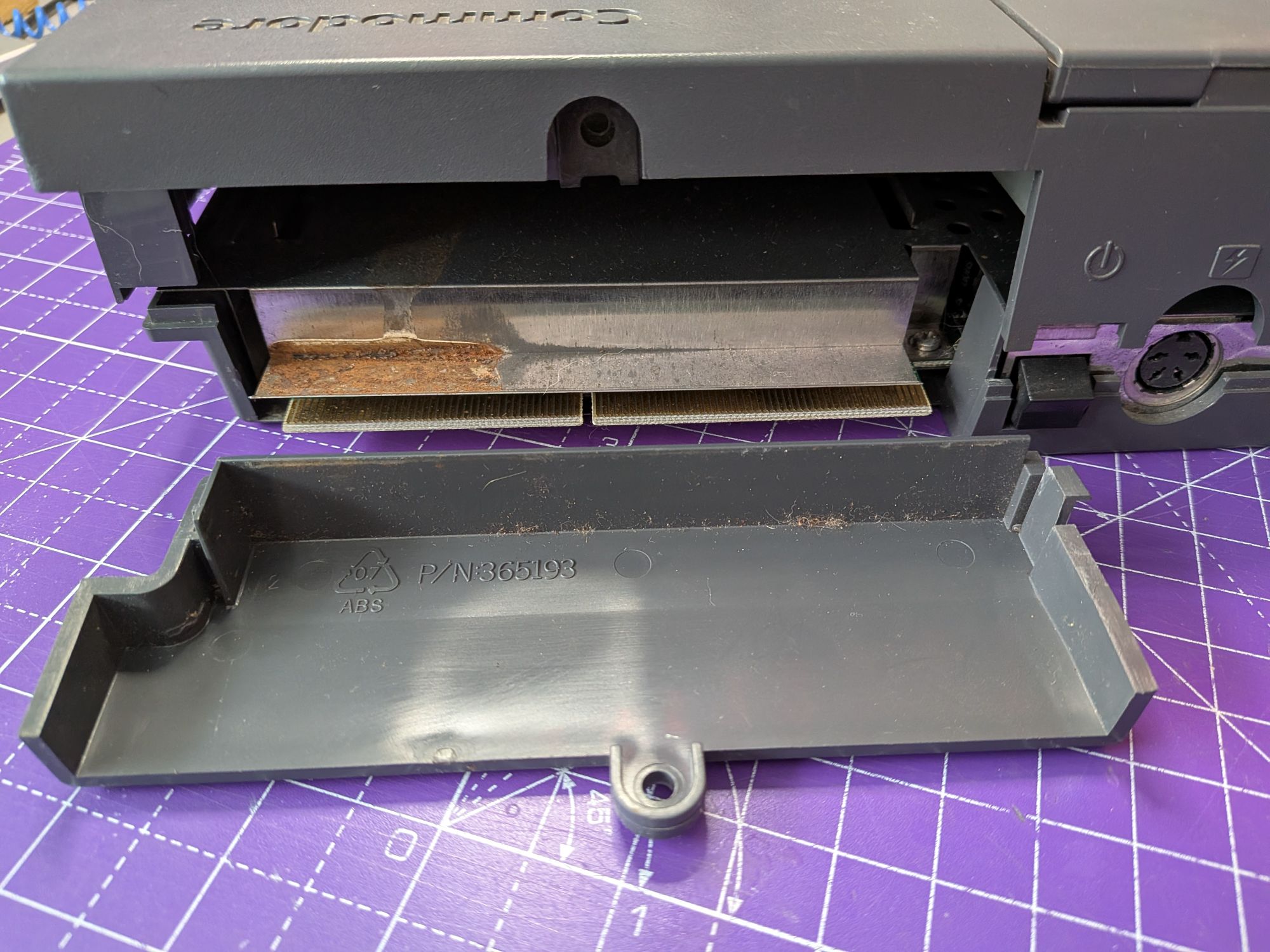
This was reported as taking a long time to boot up but once it did come to life, it read discs and played games without issues.
That’s a sure sign of ageing capacitors and as with other Amgia models, the CD32 is sadly renowned for leakage. The leaked electrolyte is mildly corrosive and over time it can cause devastation to the board. The fact it does still work once booted is good though.
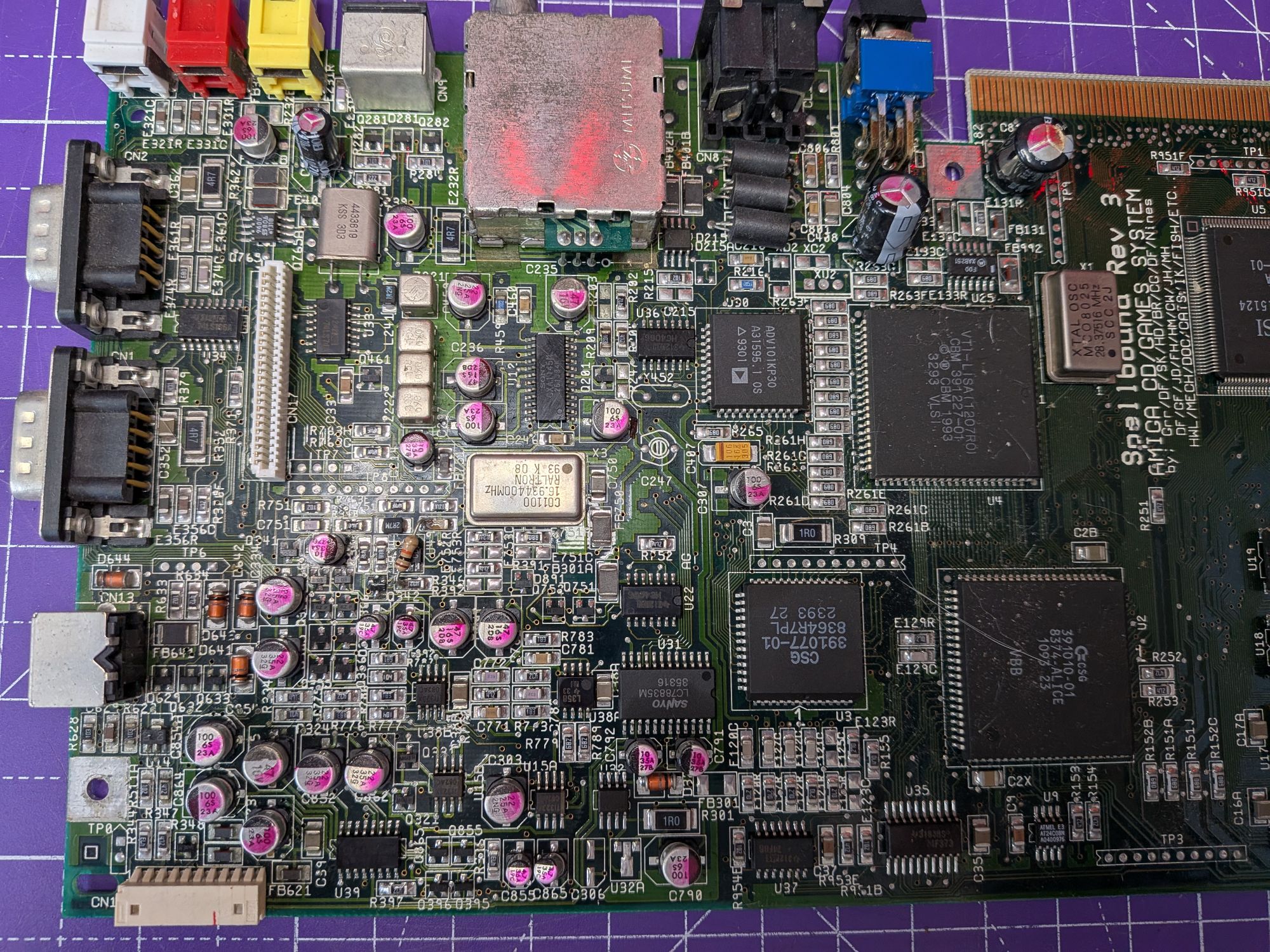
We’re going to be replacing all the electrolytic capacitors. There are a few through-hole radial type but the majority of them are surface mounted.
Getting inside is fairly simple. There are a handful of screws underneath and the top of the case, complete with CD drive lifts off. There is a ribbon cable and bundle of wires connecting the board to the top half of the console on the left hand side, so lifting carefully from the right hand side.
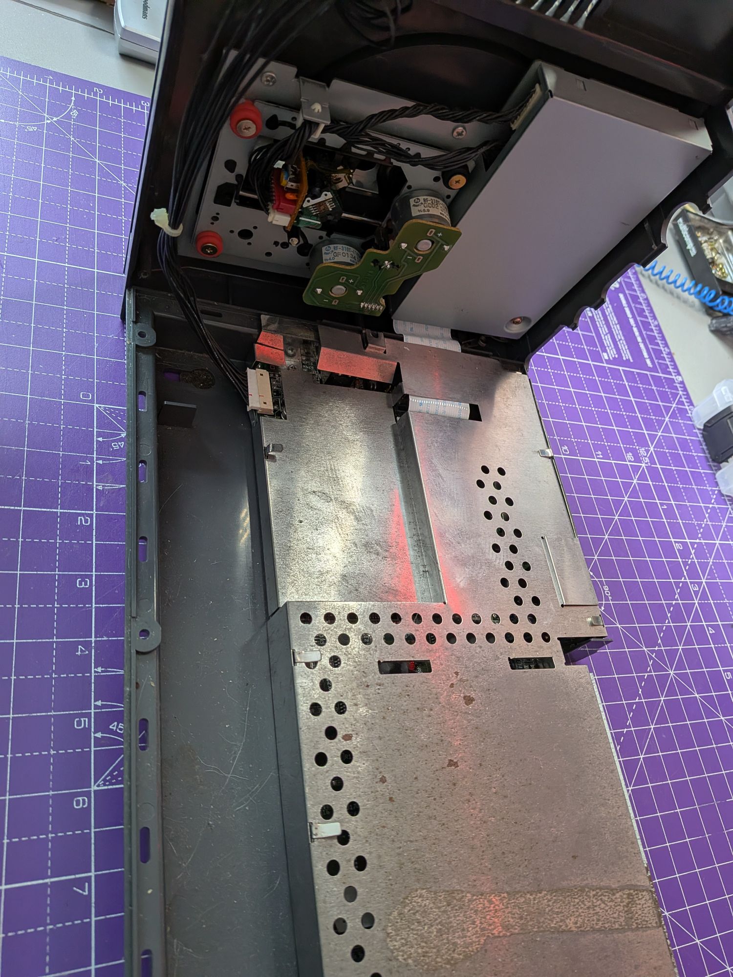
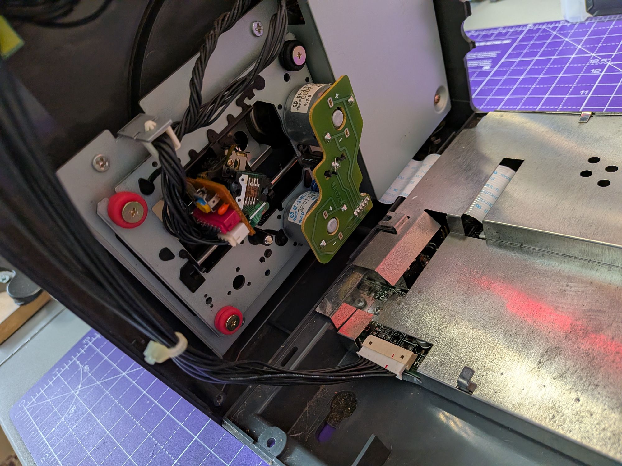
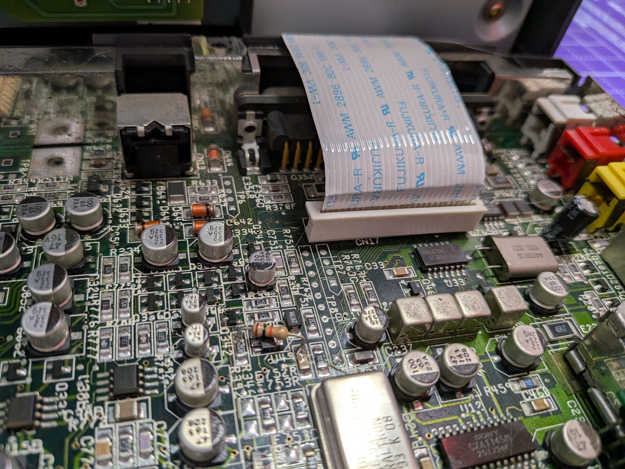
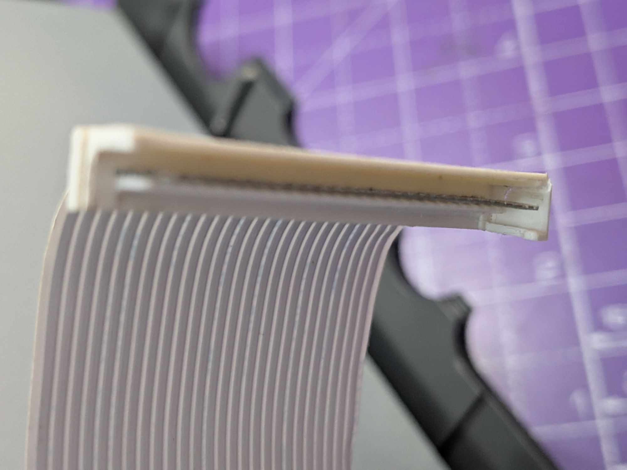
It was slightly awkward to get into this one as the drive ribbon had been trapped beneath the RF shielding, rather than threading through the gap. It left very little slack which made it impossible to disconnect without first removing the top of the shielding.
With the top off though, the reason became apparent. The ribbon connector on the board had been damaged at some point, so the ribbon was trapped to hold it in place. It had obviously worked, so as long as it will hold firmly and make a good contact it can go back together the same way.
The white plastic piece you see on the end of the ribbon, with it unplugged, is actually part of the socket. It is a ZIF type socket, zero insertion force, which in theory makes it easy to insert and remove the ribbon cable.
Over the years though, the plastic becomes brittle and they are easily damaged. If it is a problem afterwards, we can look to source a replacement and fit a new socket. It has survived this way though and been working well, once booted, so is likely to be OK.
The other wire bundle connecting the top to the board are for the lid switch, reset button and volume control. They just unplug.
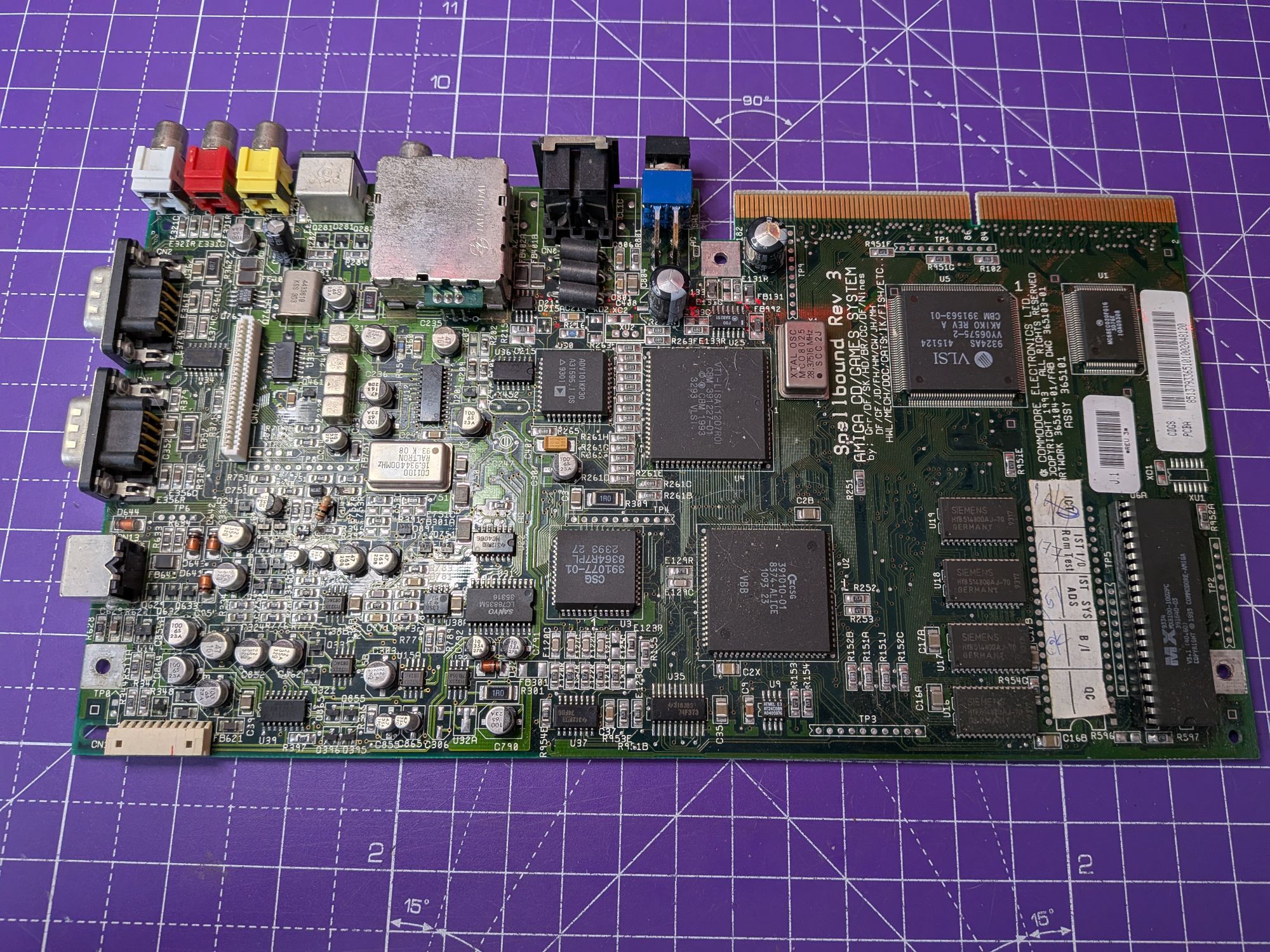
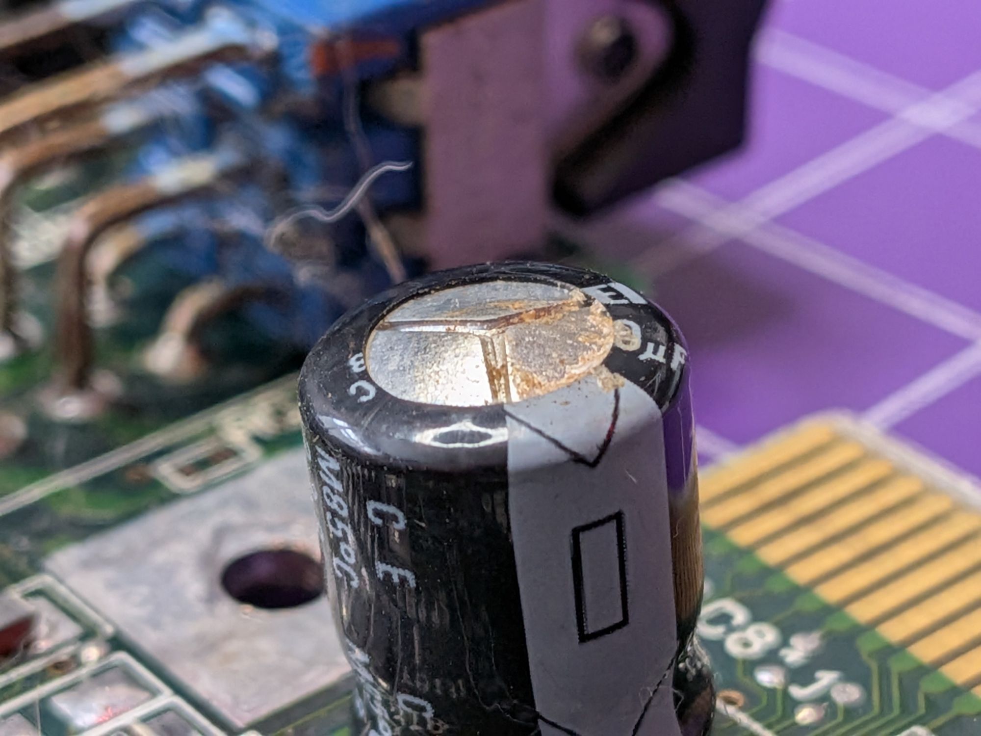
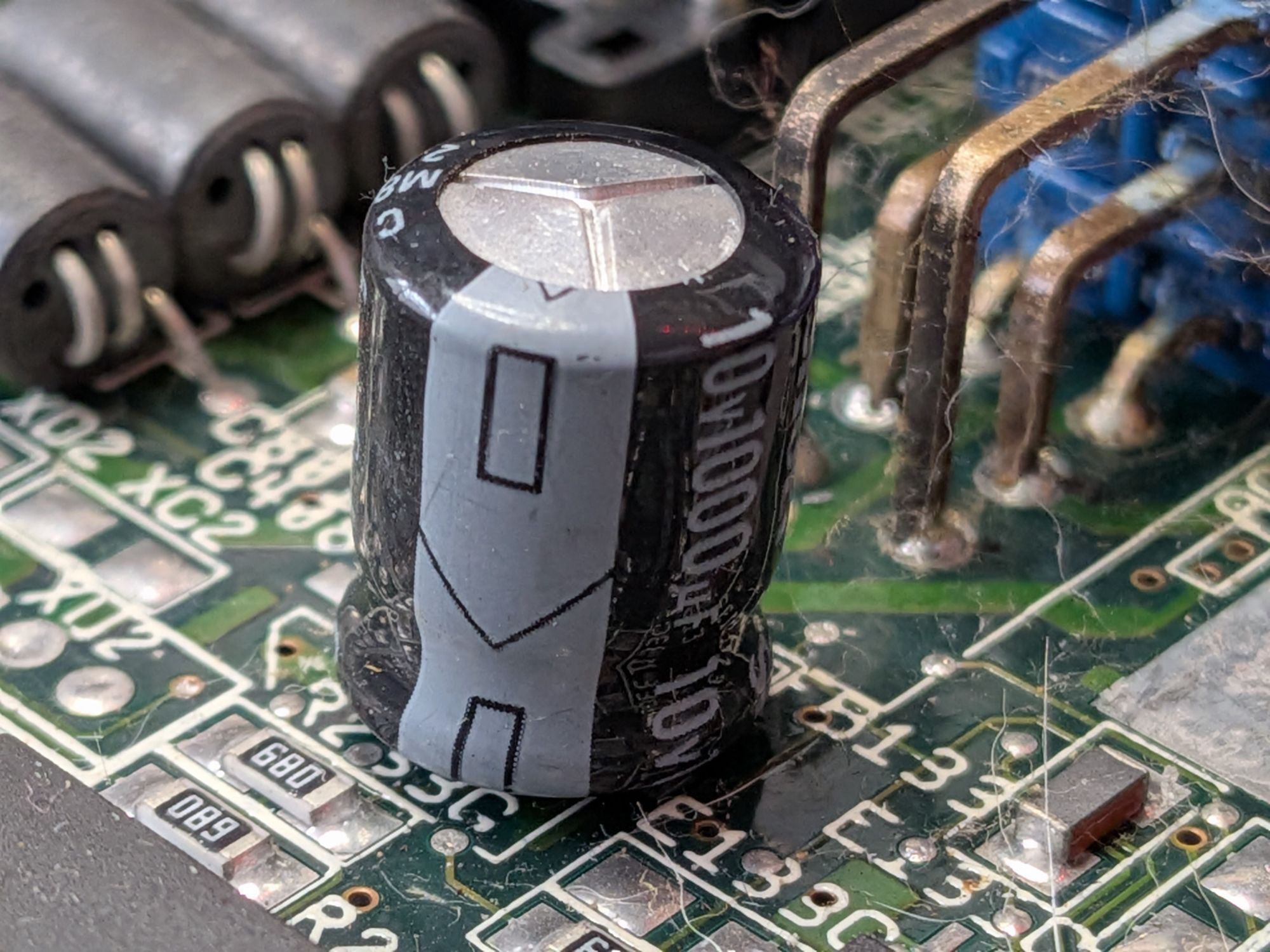
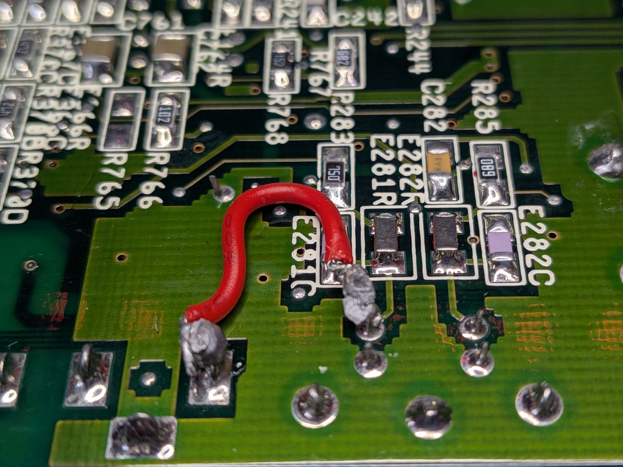
With the board out we get to assess the overall condition, and it looks fairly good. The two through hole capacitors near the power switch were domed and one had vented, which is likely what was causing the system to boot so slowly – literally a couple of minutes. There was some initial signs of leakage from the surface mounted capacitors but no real visible corrosion.
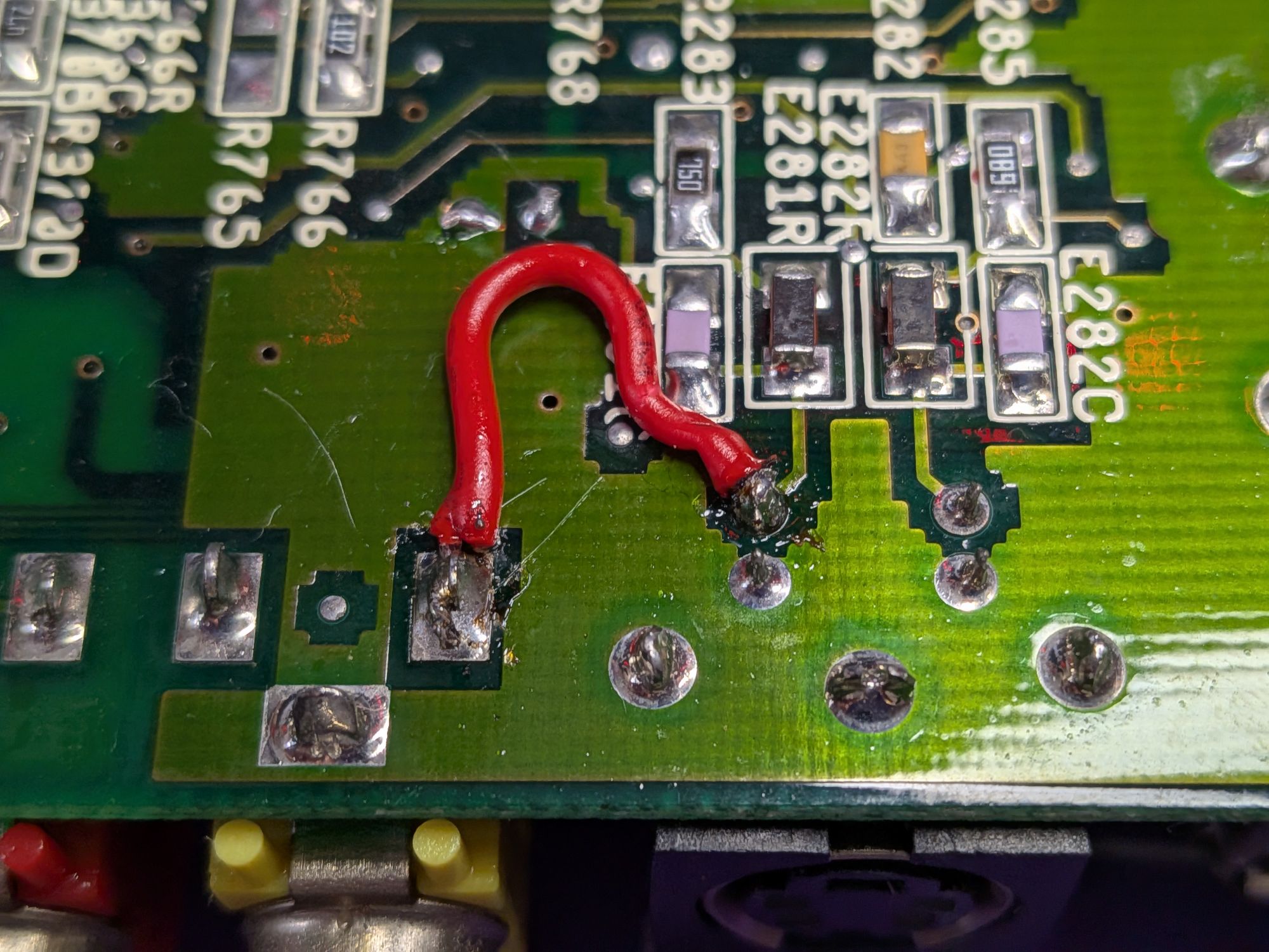
The CD32 had been modified to work around a common issue with the video output on certain Amiga’s. The red wire in the last pic connects the Luma output of the S-Video connector across to the Composite output.
They use a Sony CXA1145M video output IC, which relies on some external filtering. Commodore made use of some purpose built components as a bandpass filter on the Chroma and delay line, to resynchronise the Luma. These are the 4 square aluminium cans towards the left hand side, Z221 and Z222. It is actually 2 components, but appears to be 4. To their right are 3 leaky capacitors and to the right of those is the CXA1145M.
It can be a bit of a problem area. The capacitors age and begin to leak and unfortunately quickly cause damage to the tiny filter circuits inside the nearby tin cans.
No replacements are available for these, sadly. The manufacturer has long gone and it is kind of old tech now. I’ve not heard of any development for modern replacements. If you’re aware of anything, please let me know.
The symptom of these failing is a loss of synchronisation with either the Luma or Chroma, or as it is here simply no sync pulse or out-of-sync sync pulse on the composite connection. You commonly find the colour is missing, or rolling, or the whole picture rolls. The red wire makes use of the Luma signal to bypass the composite sync altogether and provide sync-on-luma, restoring the composite output.
A better work around is to replace the CXA1145M IC with an upgraded version, the CXA2075M, which has the filtering and delay line built in, so doesn’t require the external components. It requires some minor modifications to work here.
Checking the circuit diagram, or aka schematic, for the Amiga CD32, it appears that the output from the IC is coupled through capacitors for both outputs and the Luma/Chroma are also buffered through a simple transistor amplifier, so the red wire connecting across to the composite is unlikely to cause any issues. It was discussed with the owner and decided to leave it in place for now, although we’ll tidy it up a bit.
Added some pink to the tops of the capacitors, to keep track and set about replacing them all. Another good workout for the Sequre HT140 hot tweezers. I’ve been really pleased with those – a good purchase. There’s some awkwardly positioned capacitors here where they really came into their own.
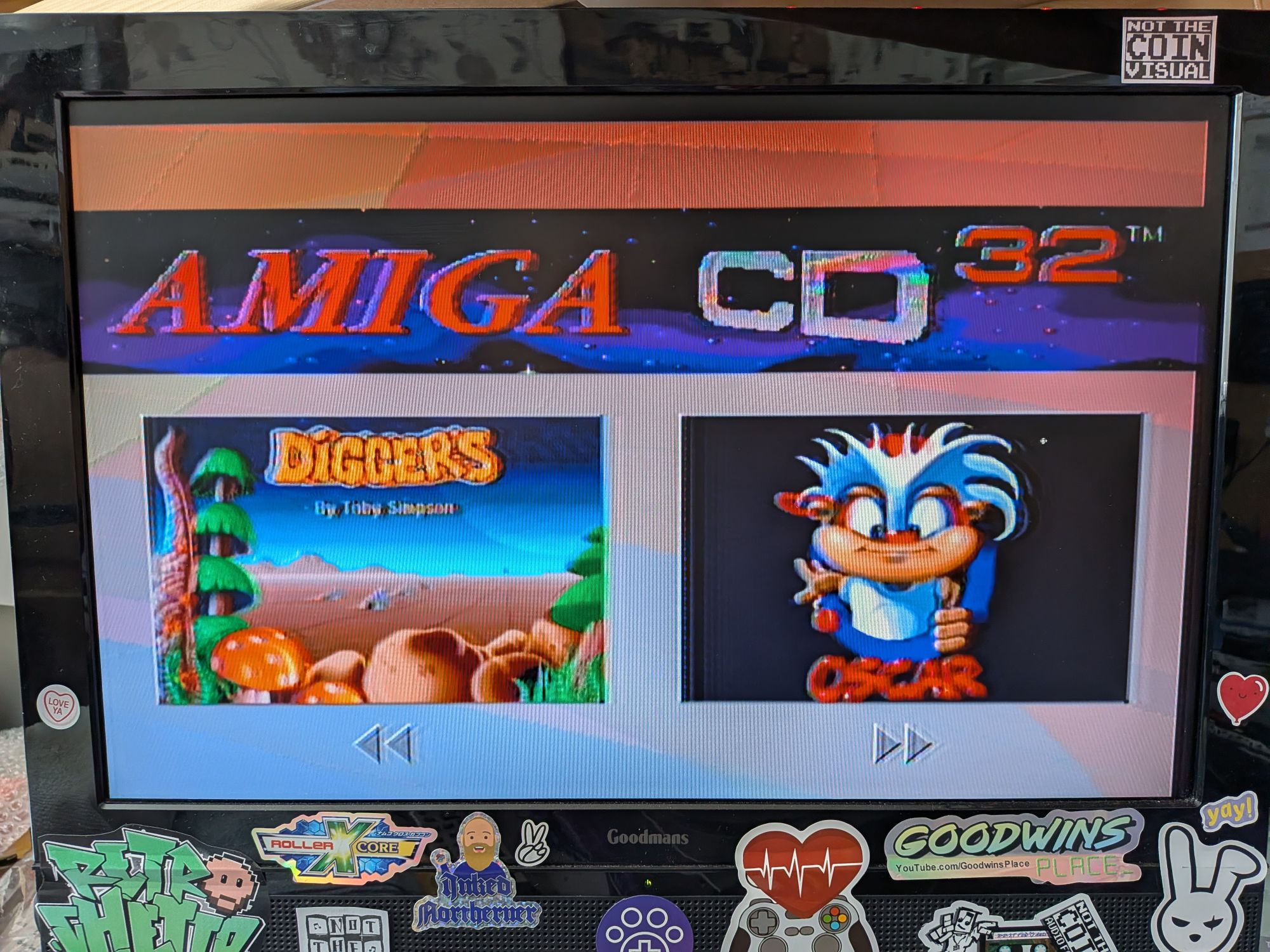
All done and everything back together, all that remained was the Play Testing! 🕹😀