


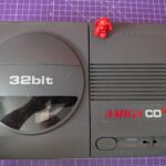
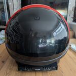
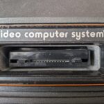
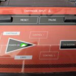
It is, isn’t it.
These were only ever produced in really small numbers, so you can imagine the astronomical prices for them now. It is in to the £thousands.
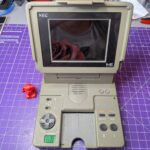
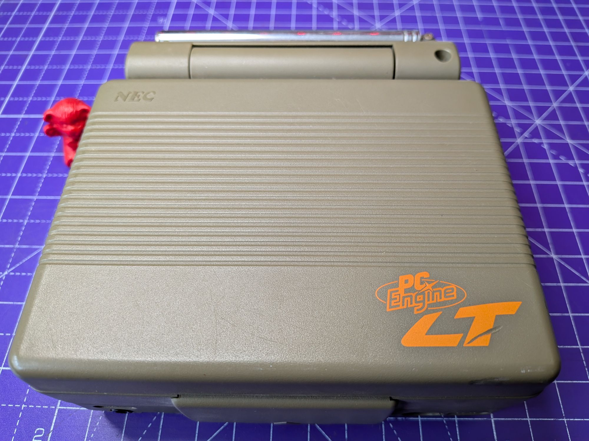
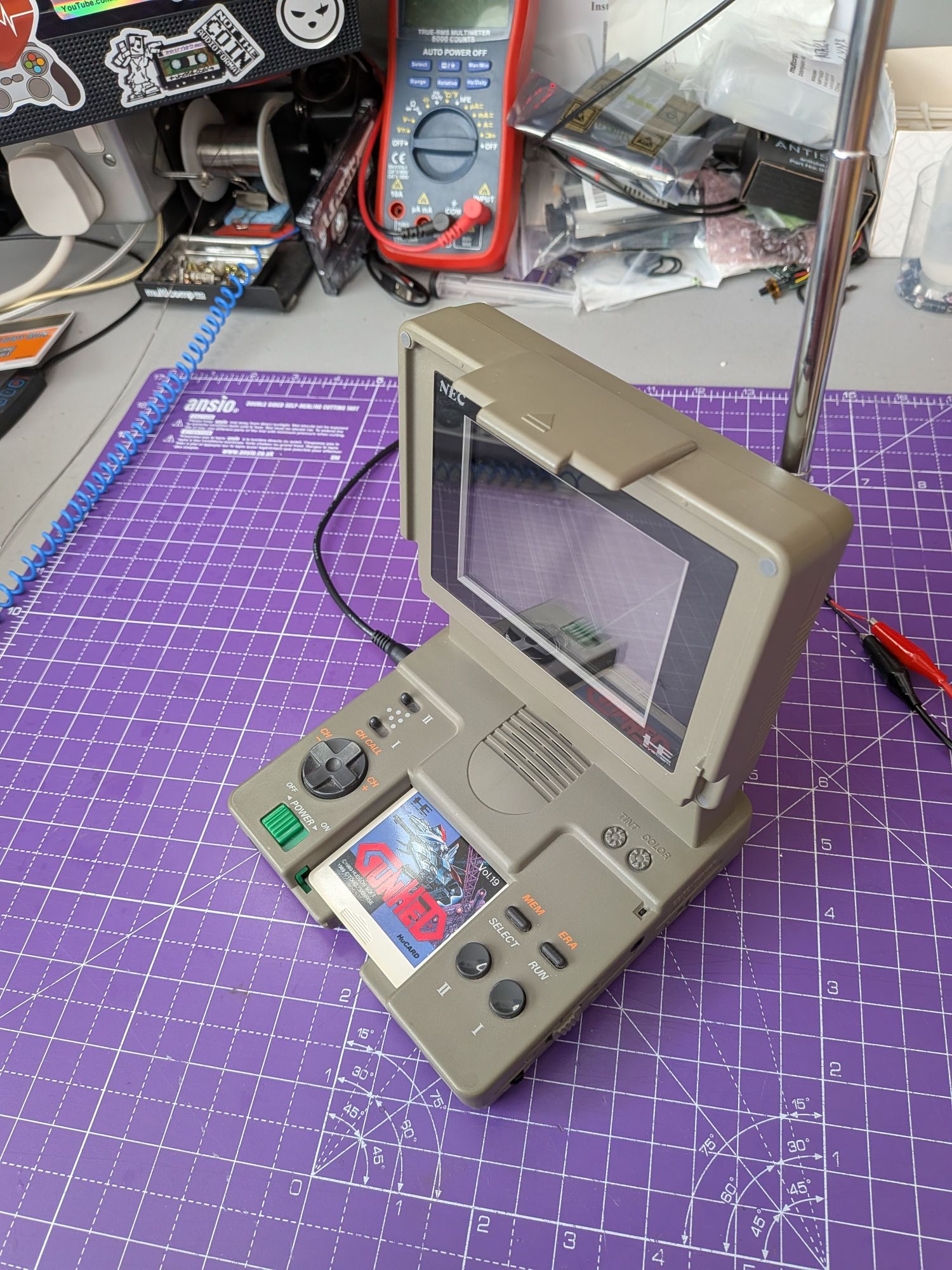
The PC Engine LT is, in essence, a portable PC Engine and TV tuner, with built-in flip up colour LCD screen. Despite being a portable system, it doesn’t take batteries, being powered instead from a small 9V socket on the left hand side. It’s actually the same size socket as the recent TurboExpress and Atari Lynx.
This one is in for some much needed maintenance. We’ll be replacing the capacitors, which do sadly leak on these, as with other PC Engine systems.
In this case, they had leaked massively, as you’ll see, but luckily not yet caused much actual corrosion.
Let’s take a tour of the PC Engine LT..
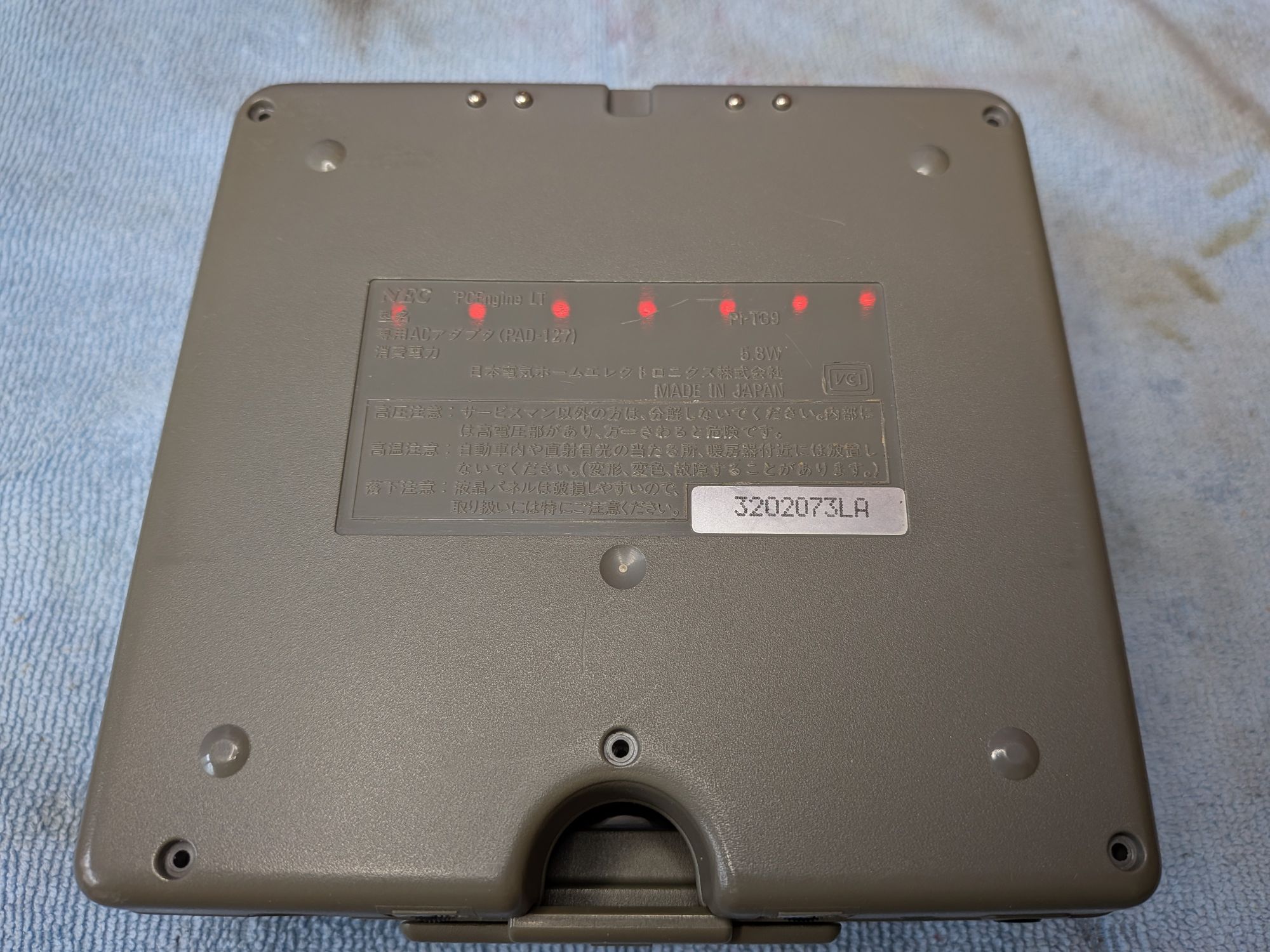
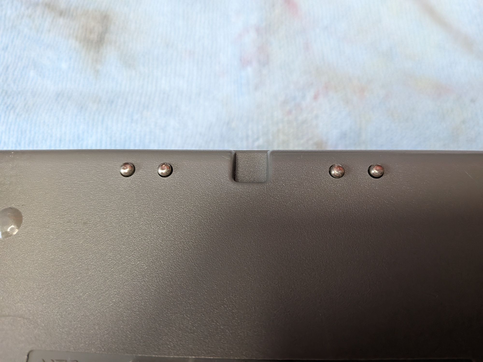
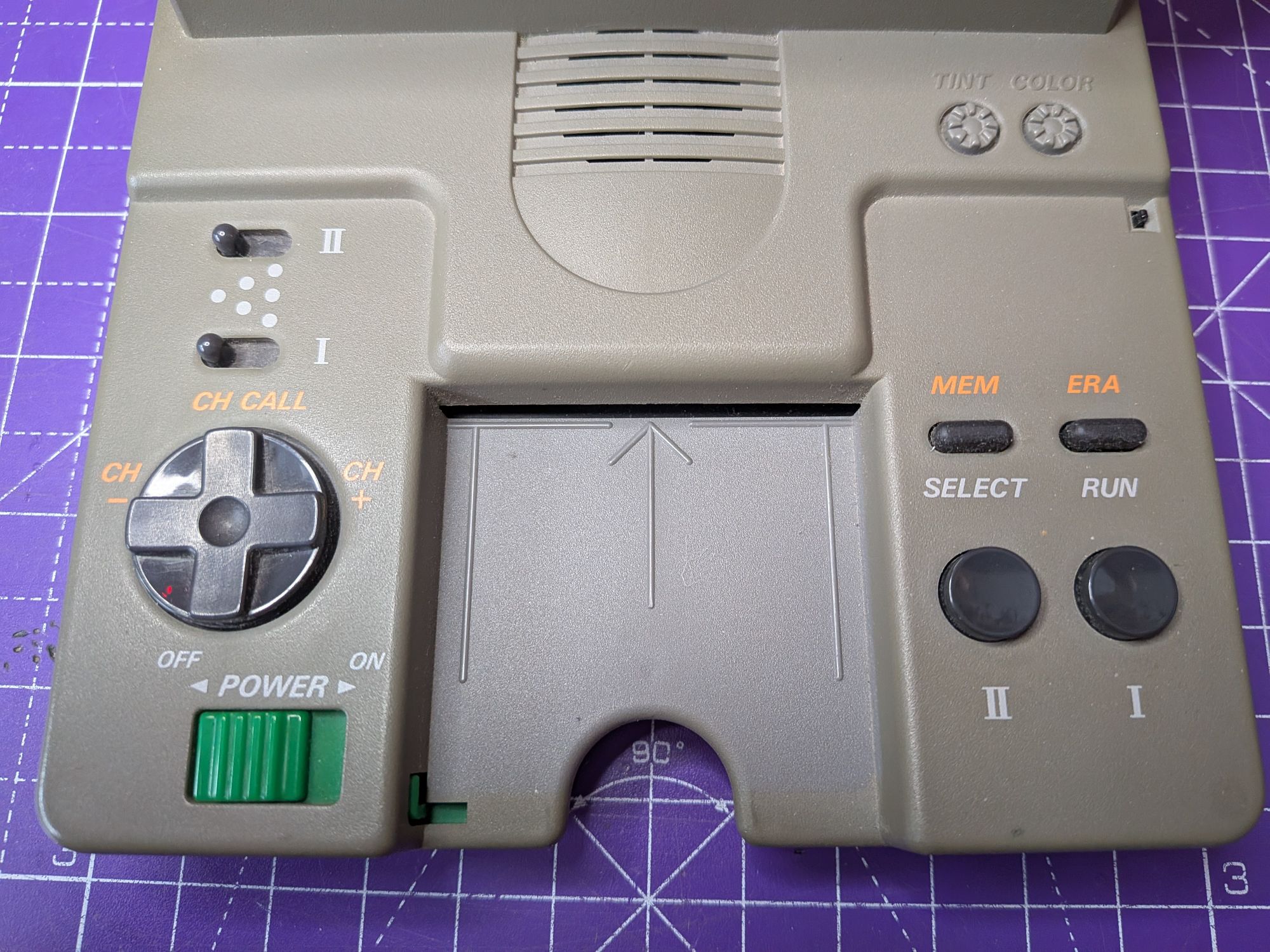
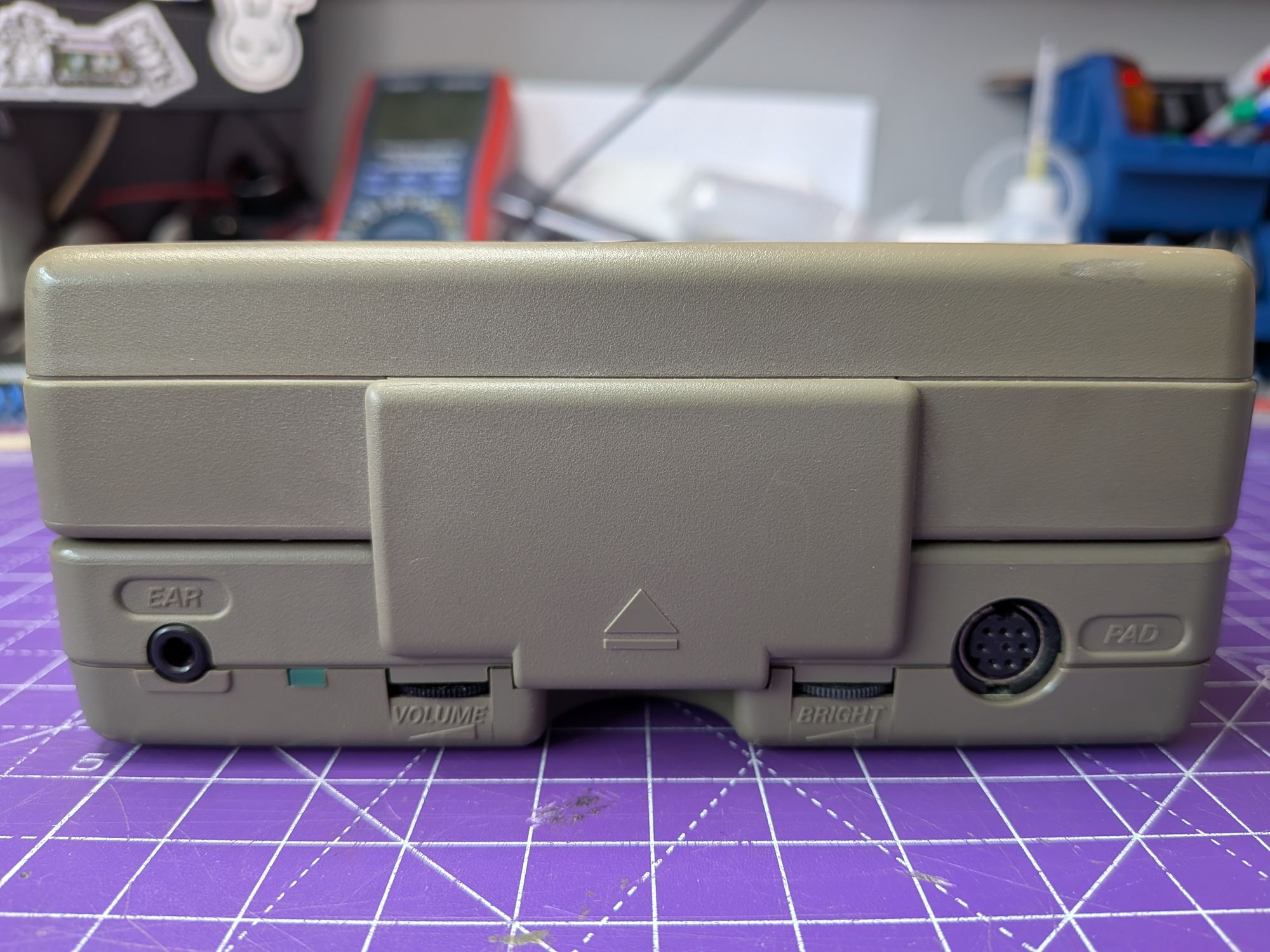

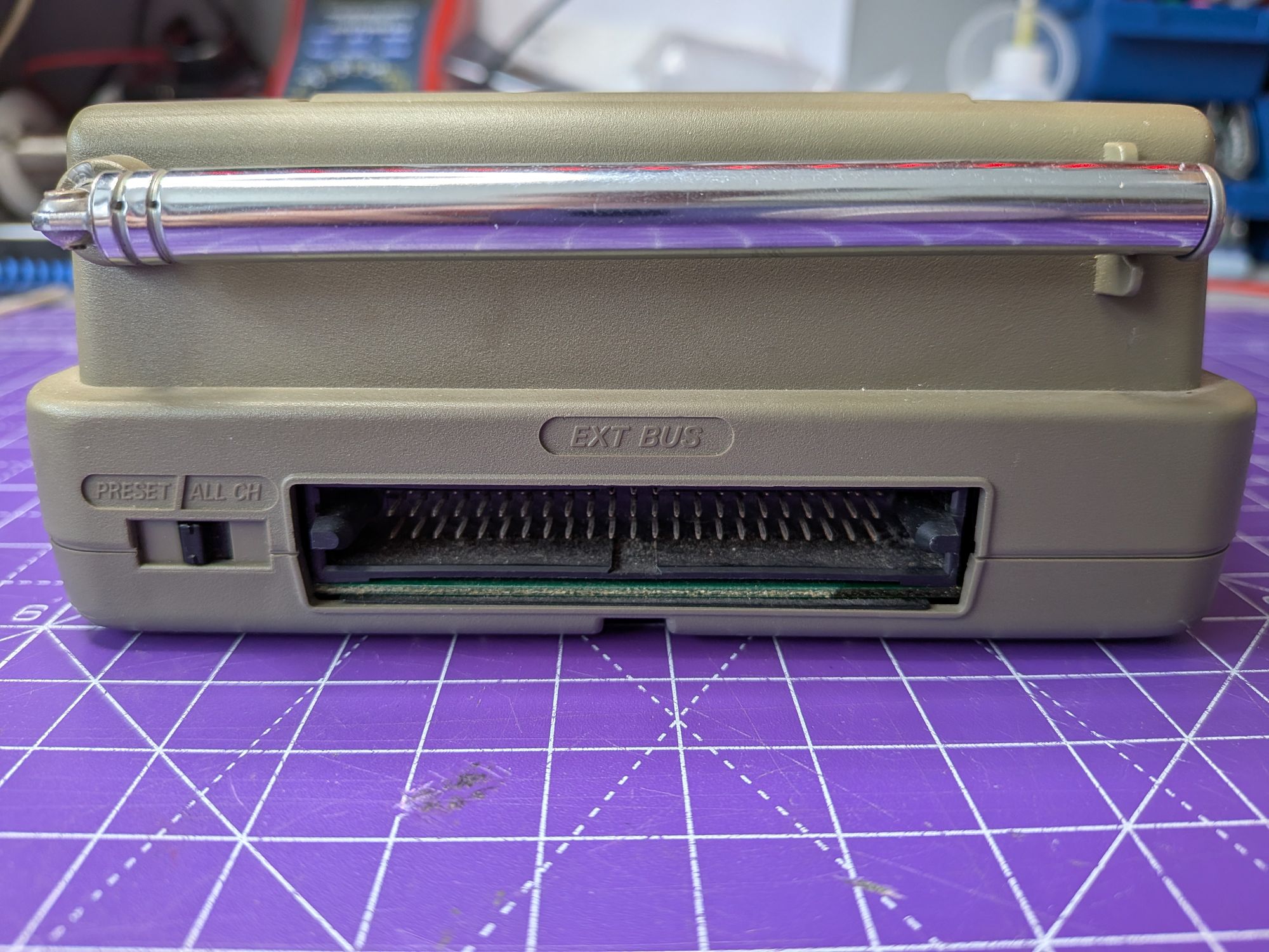
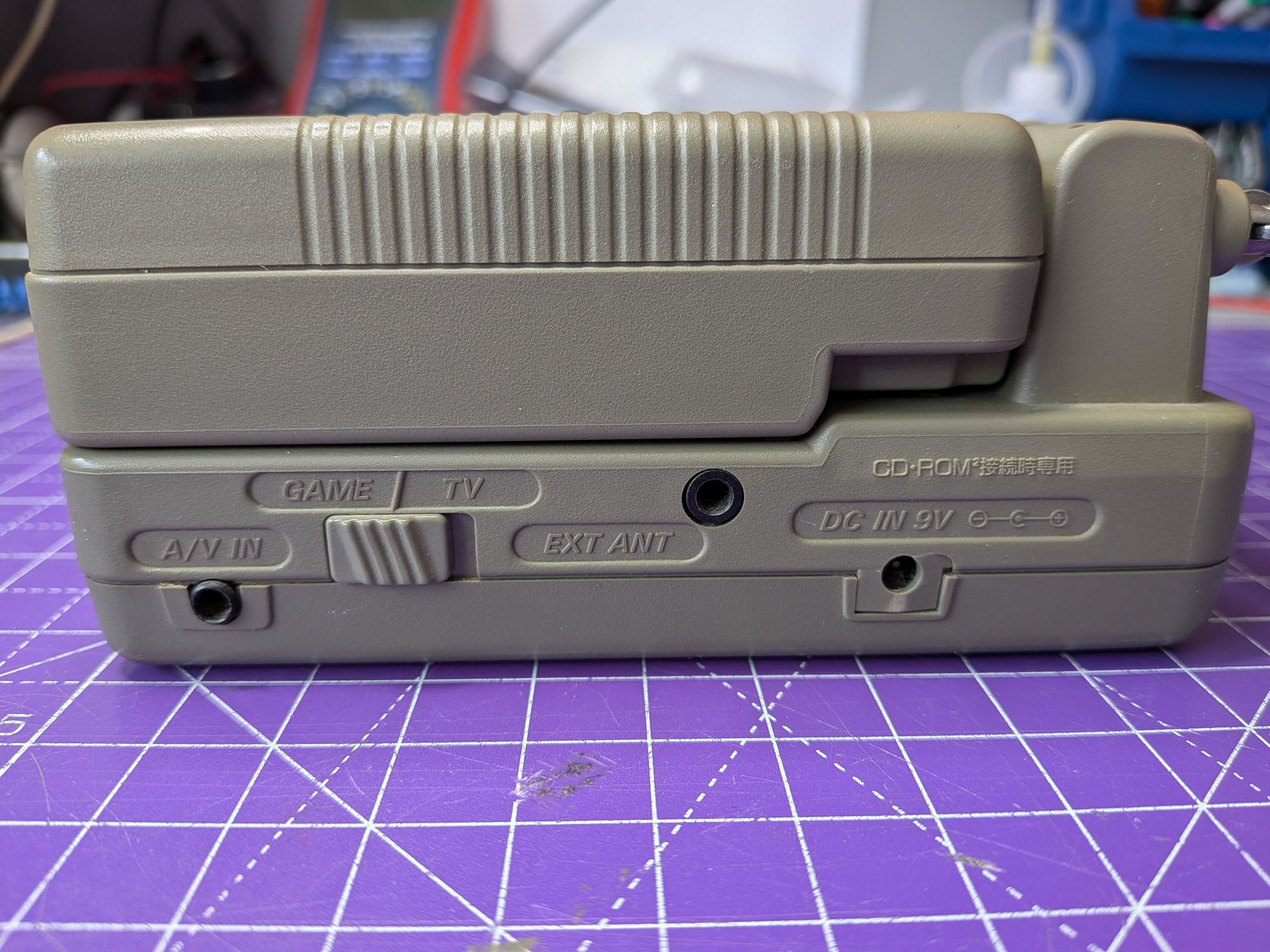
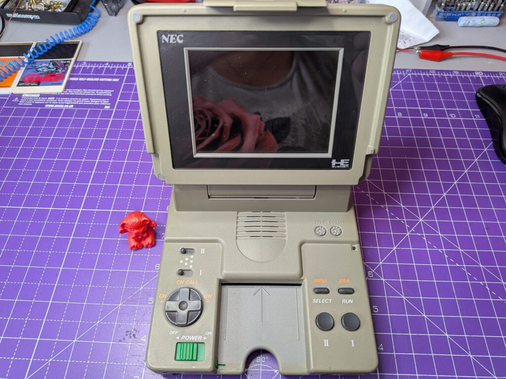
High-proof collector catnip, I’m sure you’ll agree. Especially boxed, which I believe this one does have.
As you can see though, there’s a lot going on here. The controls are also used to control the TV tuning and there are adjustments for NTSC Colour and Tint, which is a common thing with NTSC TVs, hence the “Never-The-Same-Colour” trope. The tuning is handled by the D-pad, which with the rear switch can either scan through the entire TV channels, or just between preset stations. There run and select buttons on the right are to do with that.
I love the green power switch. It is a PC Engine style one with a green piece extending across the card slot to prevent you inserting or removing card with it turned on.
The bottom of the system is more or less plain, except for 4 grounding pins towards the back. They spring slightly and would be used to connect the ground of anything plugged into the External Bus connector on the rear.
The left has just the power socket. On the right though there is a second power socket, which is used when the CD-ROM is connected, which seems like it covers the one on the left. The CD-ROM requires a special adapter, known as a PI-AD18 (I think), which is so far beyond collector catnip, it’s into the realms of unobtanium. I’ve only seen a picture.
On the rear is the Preset switch for the TV and the external bus connection. I believe this is standard PC Engine external bus connection but would hesitate to plug ANYTHING external into this. It’s such a rarity. There’s also a surprisingly long extending aerial.
On the right side is the other power socket, a point for an external aerial, an AV input for composite video and the switch to change between Game play and TV tuner. It should probably not be switched whilst turned on but has not interlock to prevent it, so may be is OK.
The front houses the Brightness and Volume wheels and an earphone socket. There’s also a controller port, so you can connect an external controller and view the 4″ screen from all the way across the room. Maybe in 1992..
It’s a pretty thing isn’t it. Unfortunately, it’s dead.
We already know that it needs recapping though, they’ve probably leaked and there’s likely corrosion, so in we go..
There are 5 small screws on the bottom. How hard can it be, right? From the outset, it’s important to say that this is one of the most challenging retro consoles to work on. Not just to get in to, as you’ll see.
With the screws all removed the bottom doesn’t come off as you’d expect. There is still a small piece of double sided tape on the card slot that sticks the two halfs together as well. It takes a bit of patience and what seems like unreasonable force but applying pressure, rather than pulling, it does eventually come unstuck.
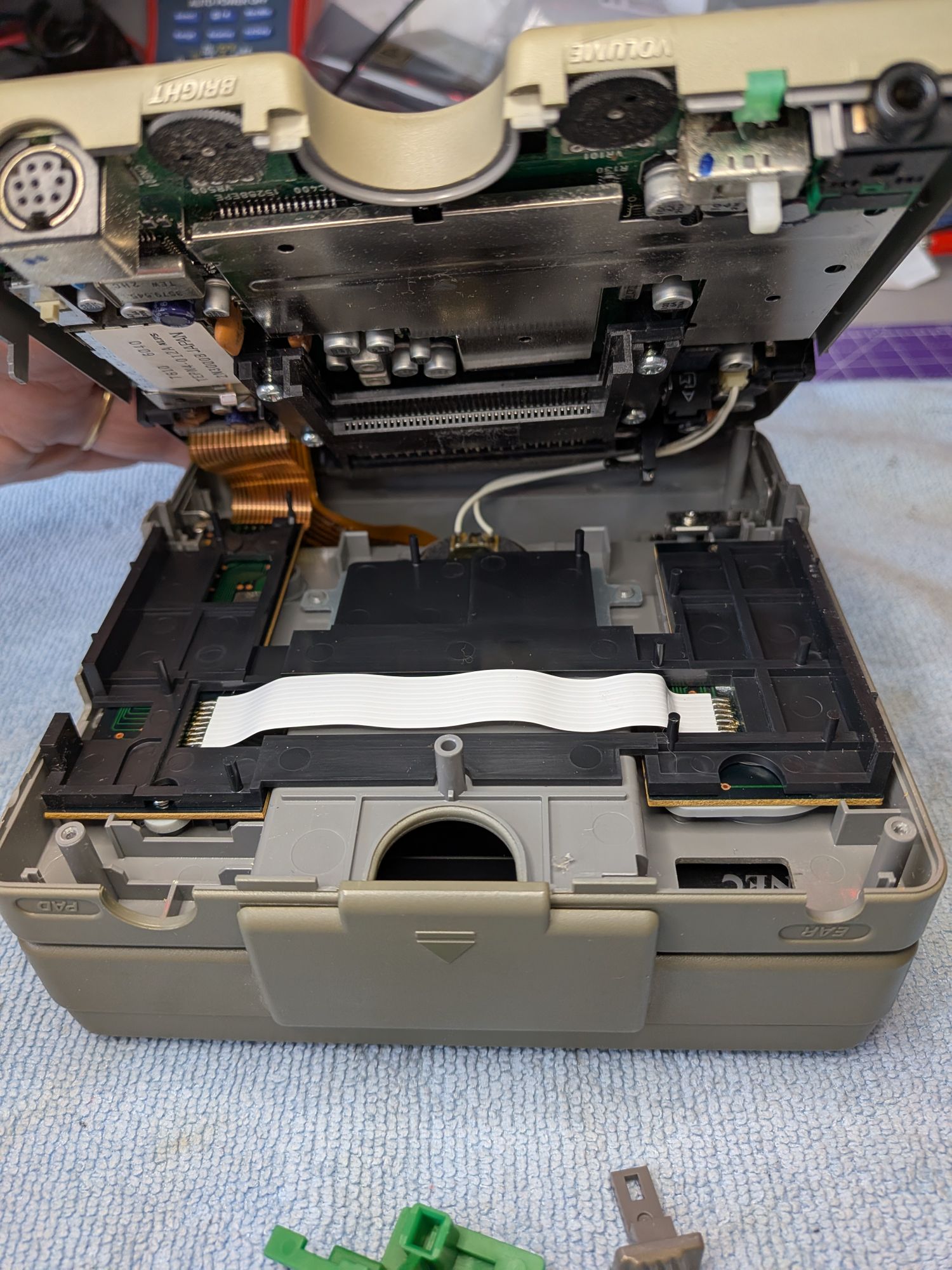
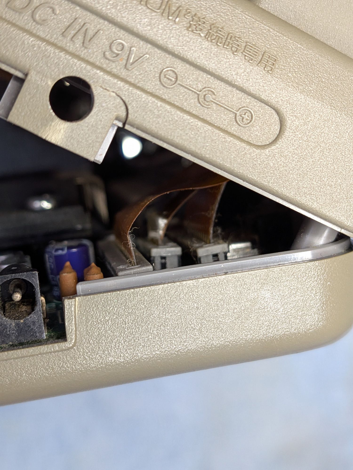
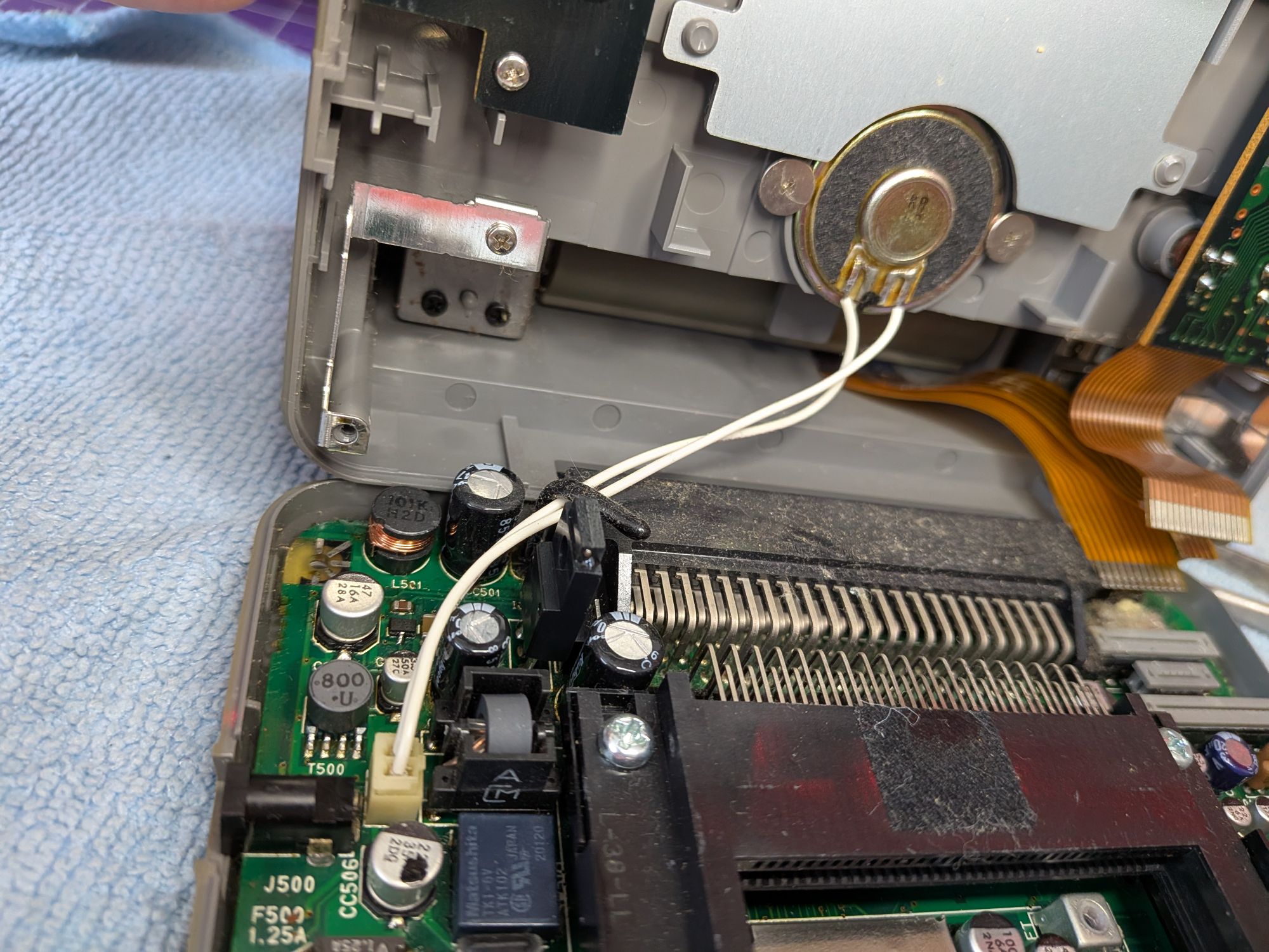
It’s important not to lift the back section, as you can see. Tucked in the rear corner are three very short ribbons, for the screen, controls, etc in the top half. Everything we need to get to is in the bottom. The top holds the screen and backlight, the speaker, the aerial and the controls, everything else is in the bottom.
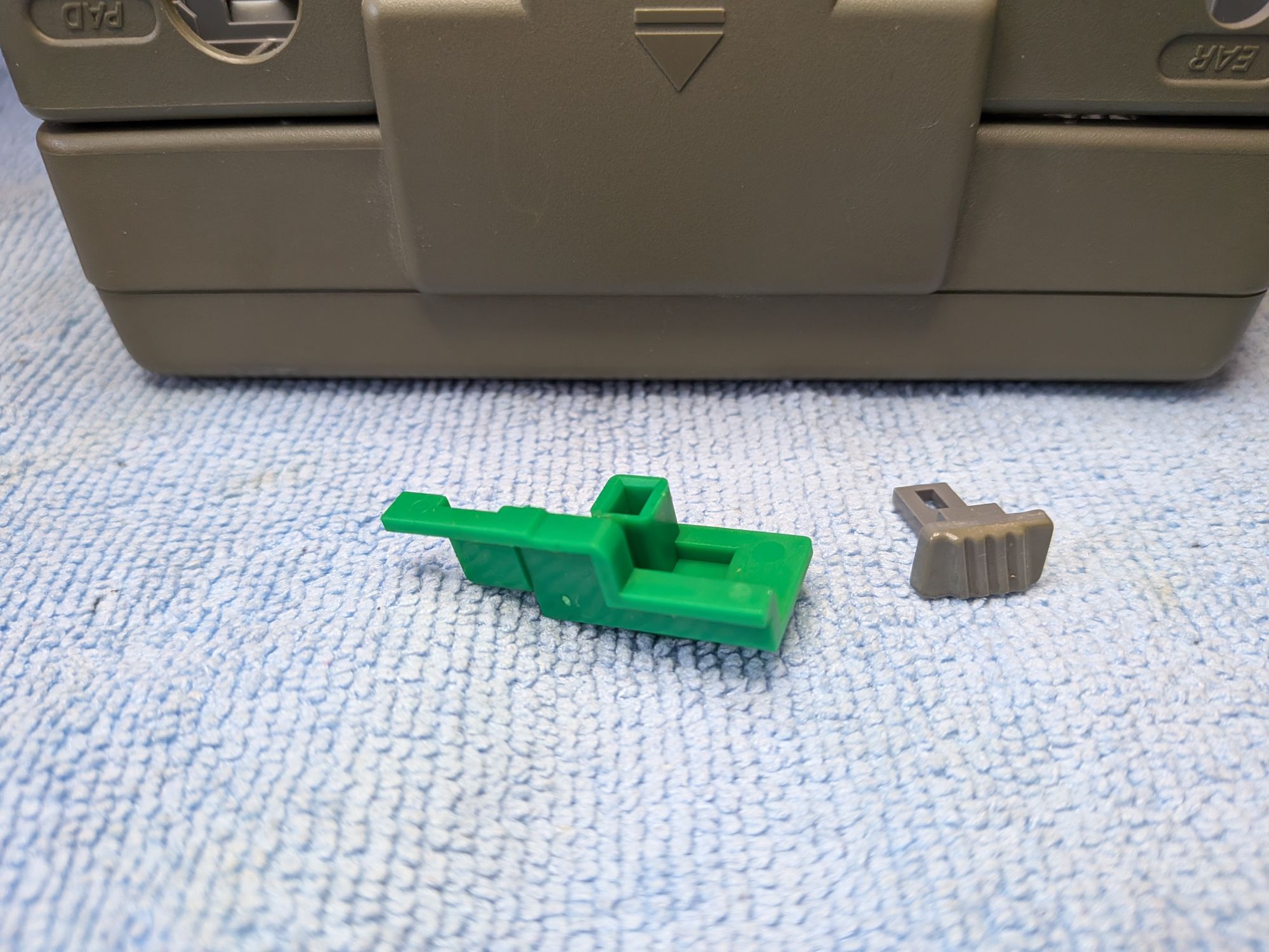
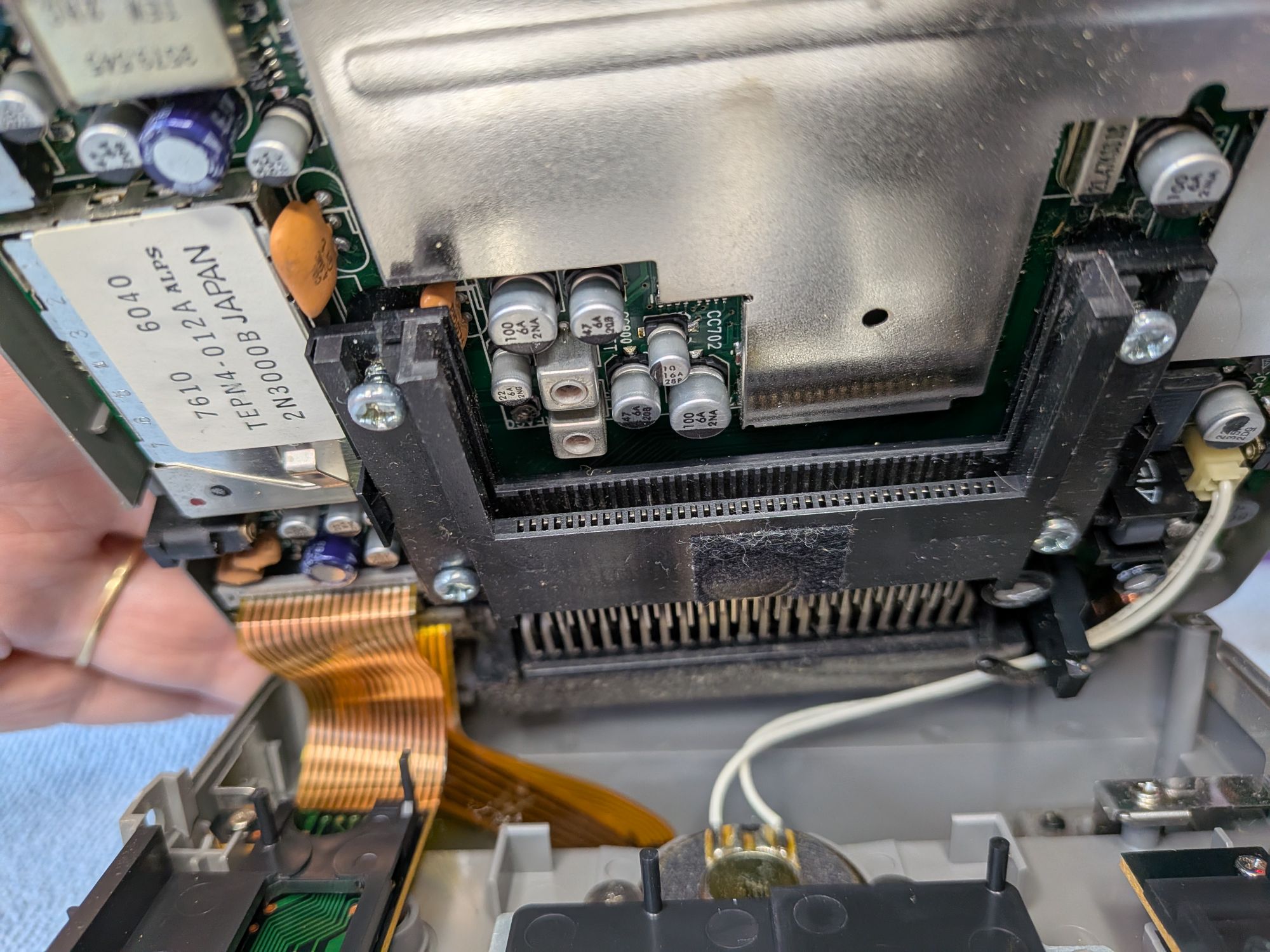
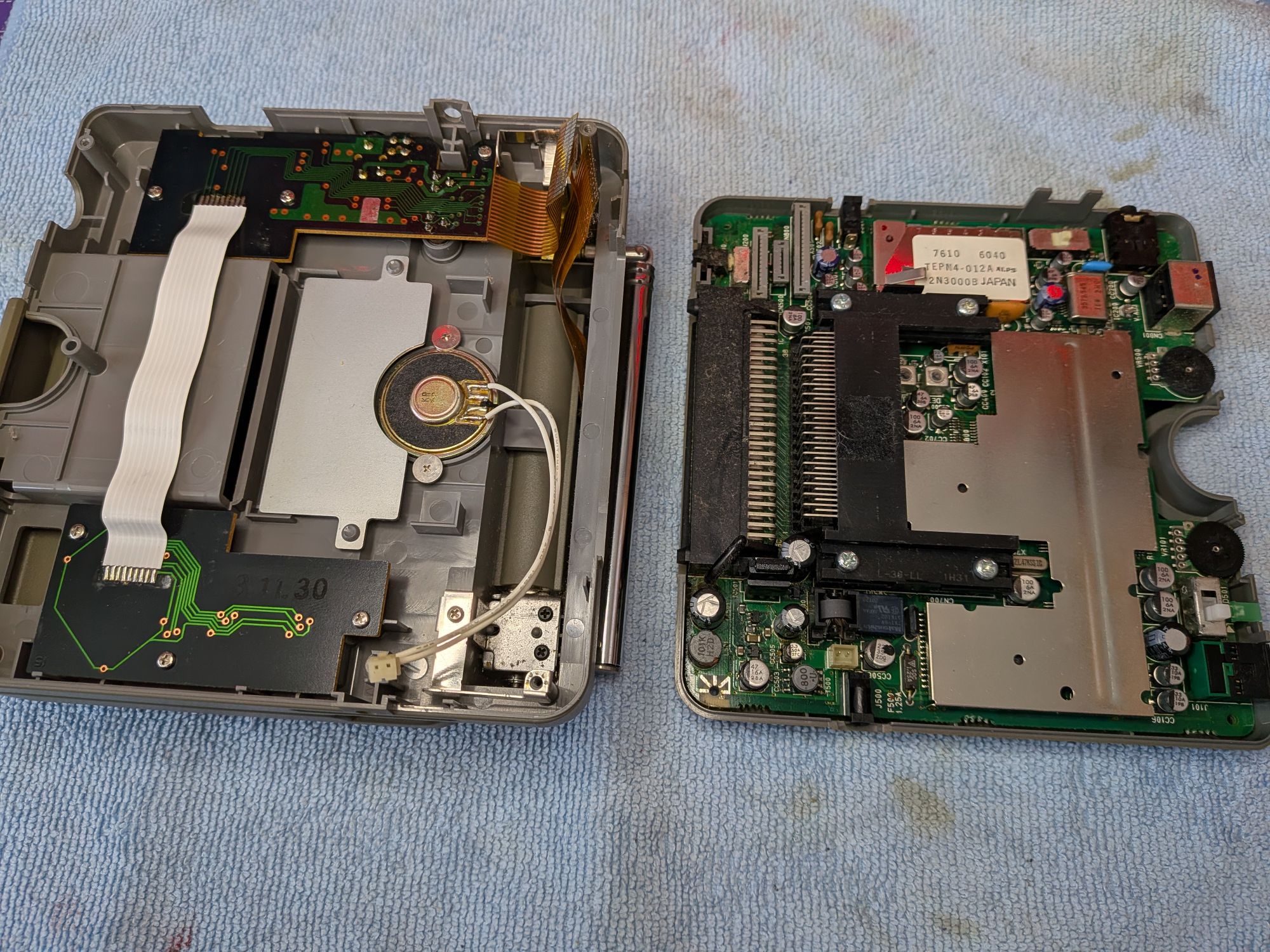
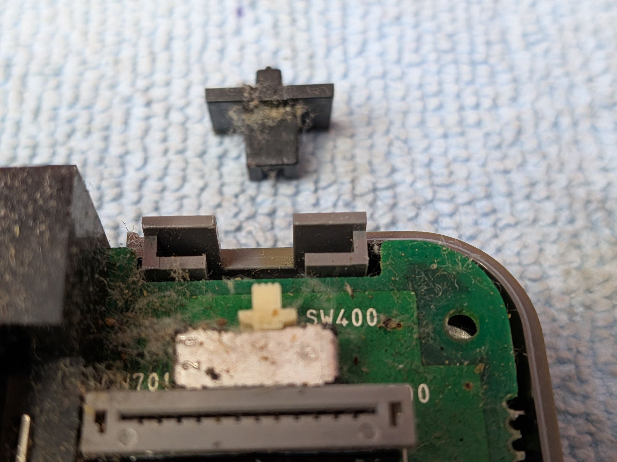
Opened from the front now you can see the 3 short ribbons in the back corner. There’s limited access to disconnect them and it’s important to avoid pulling them whilst moving it around. They will tear very easily, which would be a new world of hurt. The switch plastics for the power button and Game/TV are resting on their switches and come out at this stage.
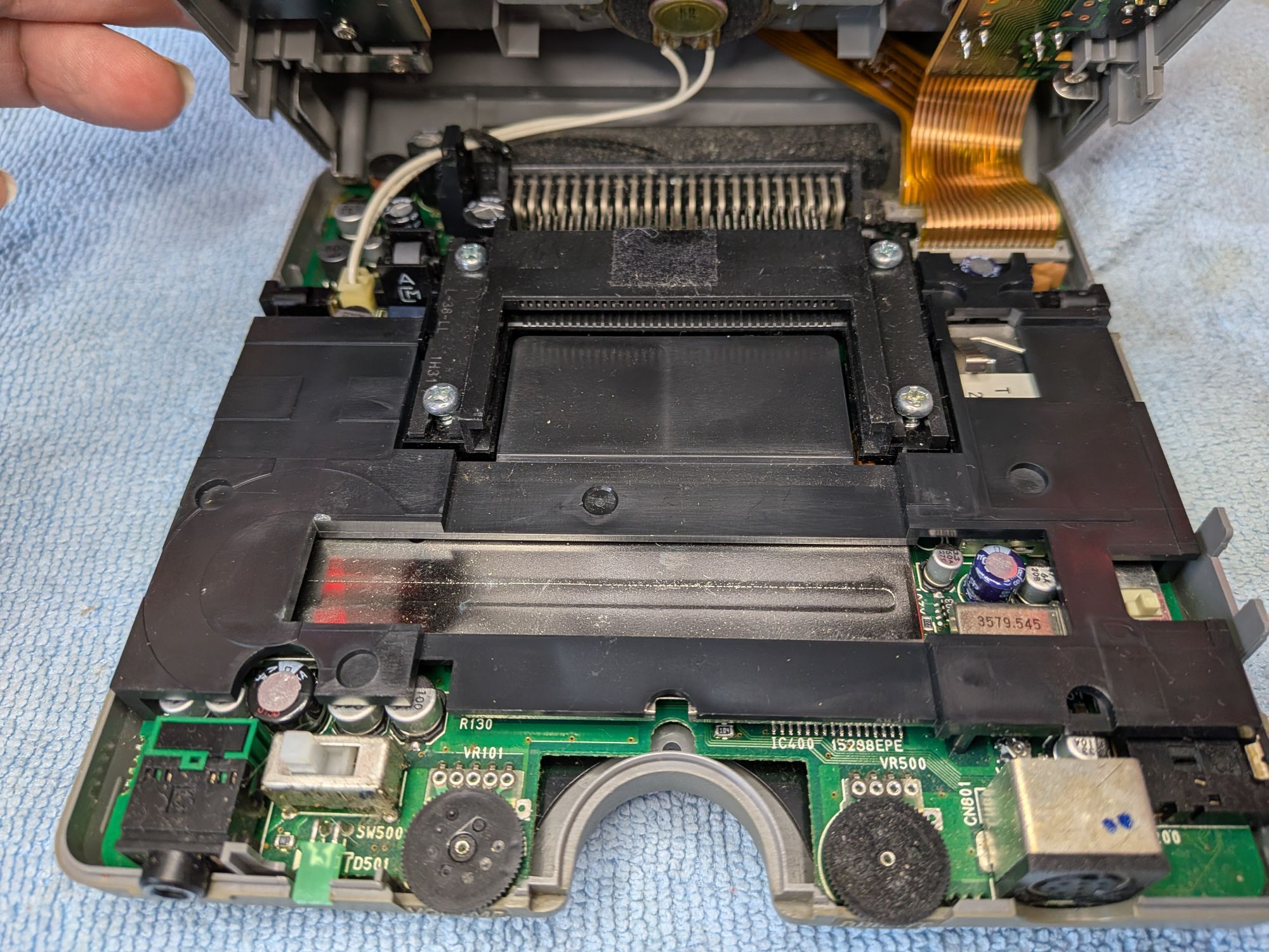
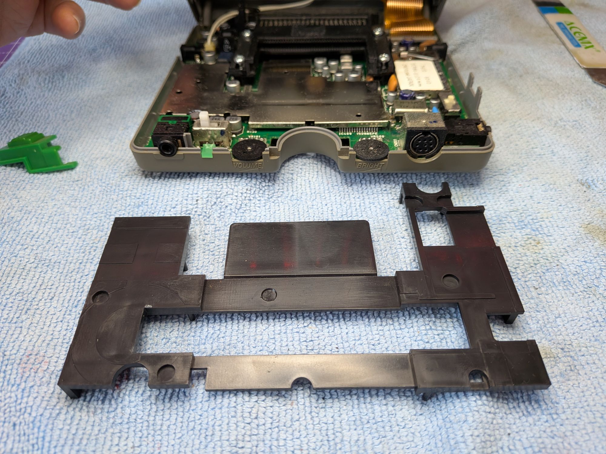
There is a large black plastic shield on the bottom half, which should just lift off. It has pegs which sit inside holes in the metal RF shield beneath it. It’s just there to guide the HuCard in to the slot. That gives a little more access to disconnect the ribbons. The white wires are just for the speaker and plug in on the other side of the board.
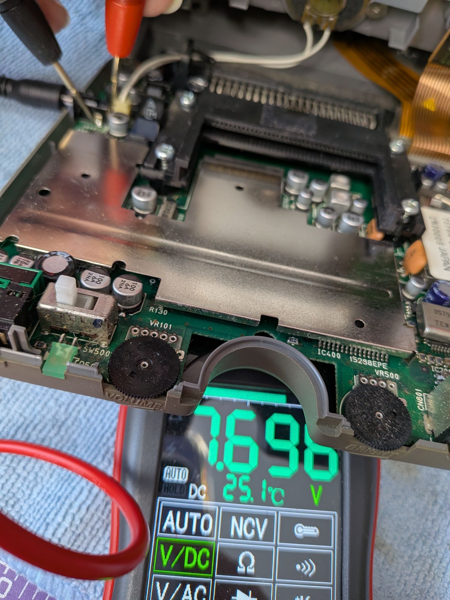
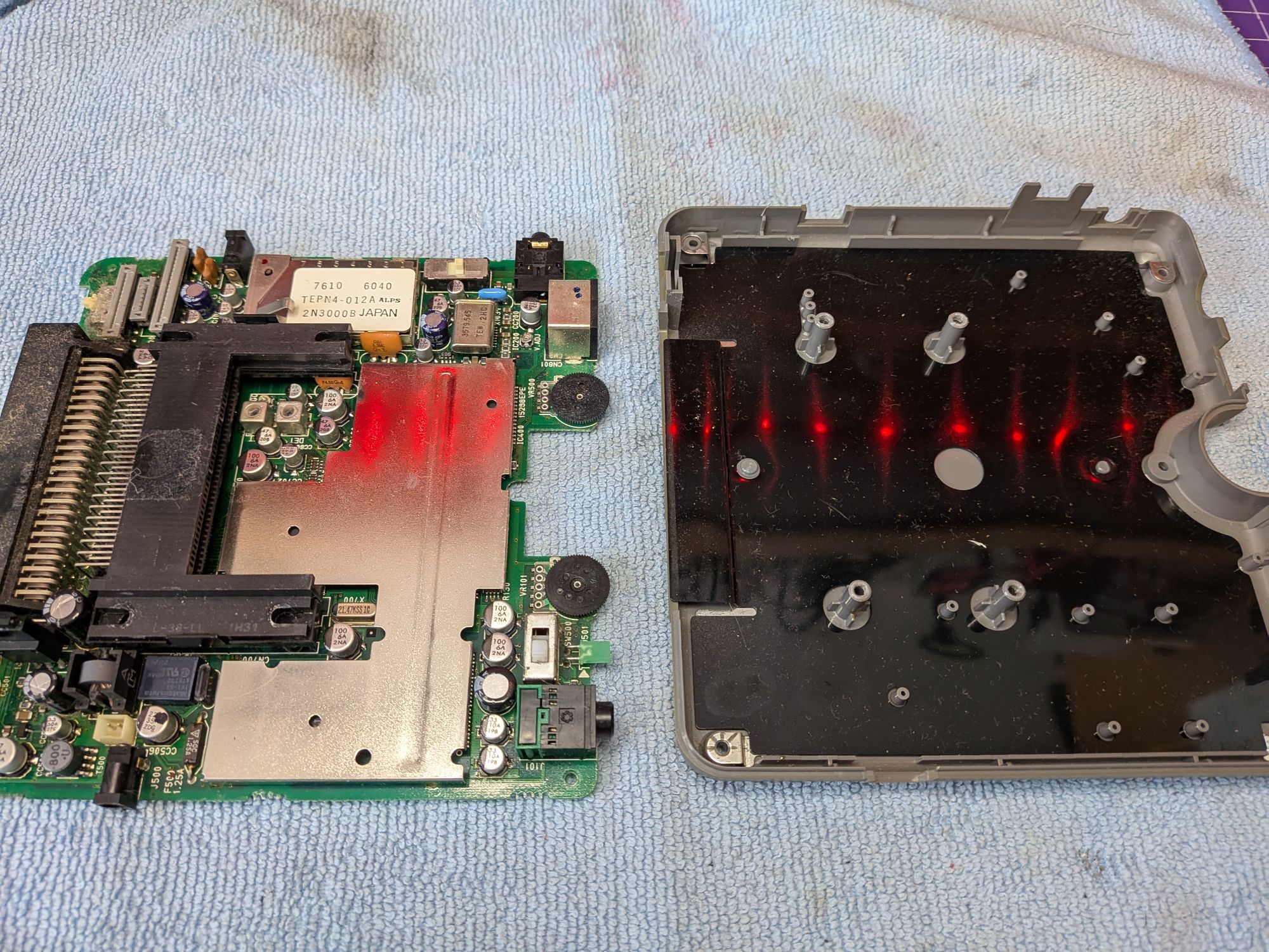
Before disconnecting all that though, it’s worth checking that power is making it through the socket onto the board. You can see here that it is.
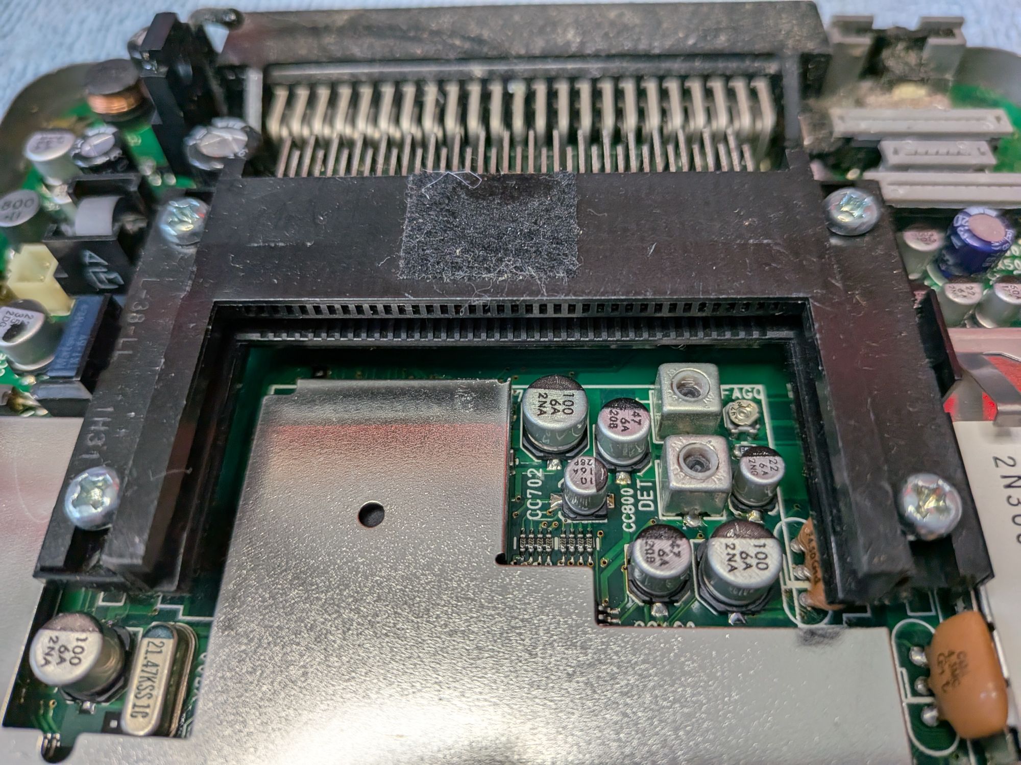
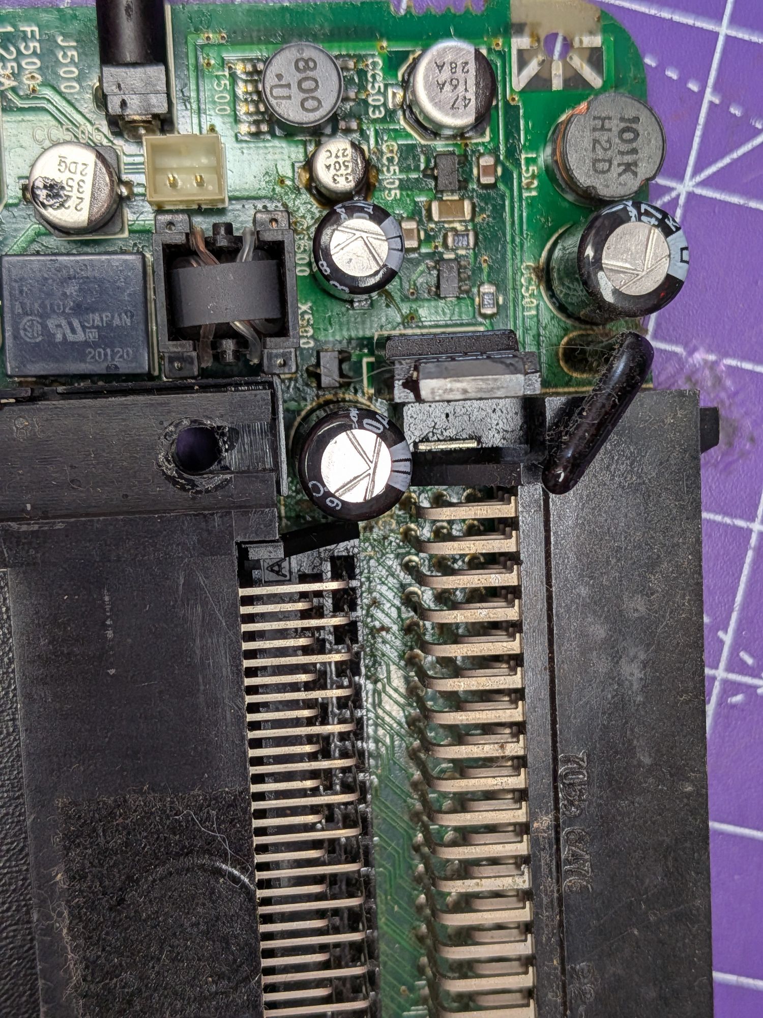
With the base removed there are 4 more screws securing the card slot, and the board, to the outer case. If you look closely, you can just about see the first signs of electrolyte leakage here. It had made it onto the card slot and was wet around the screws. Remove the plastic actuator for the Preset switch and then board then lifts out.
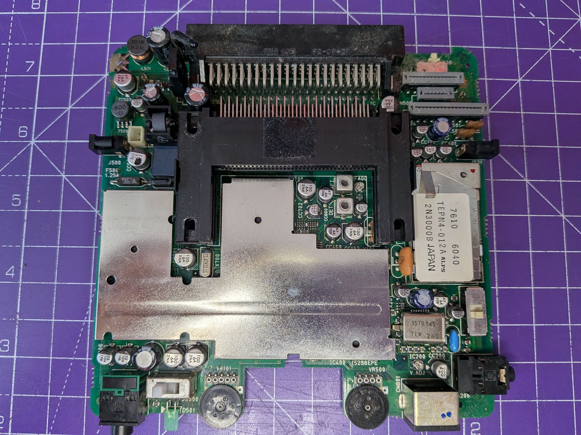
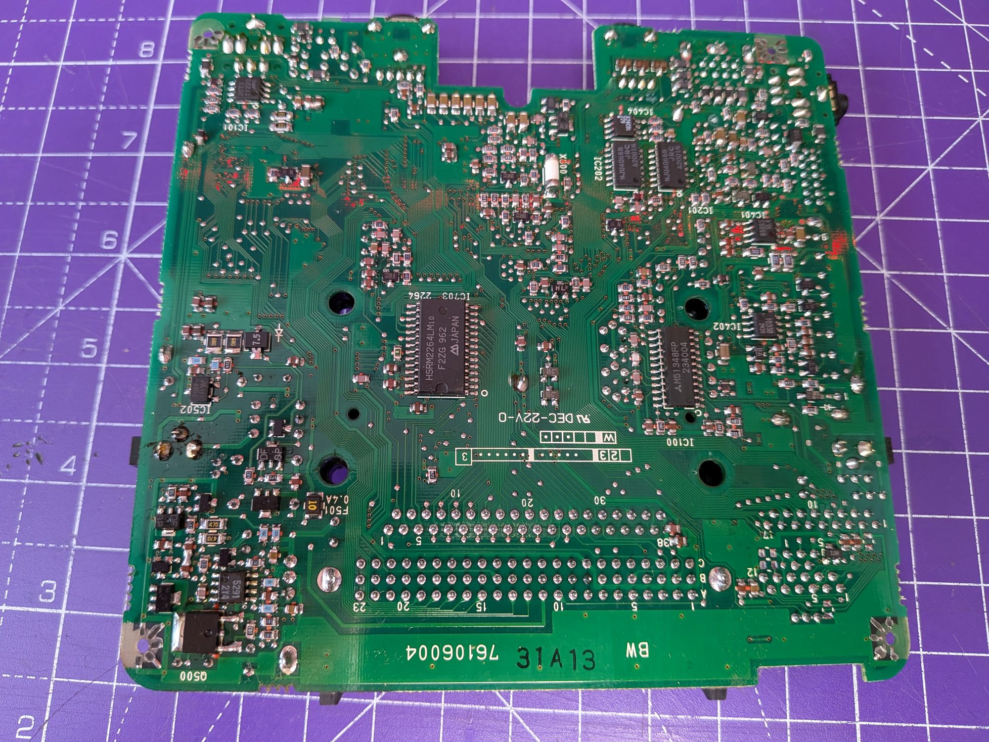
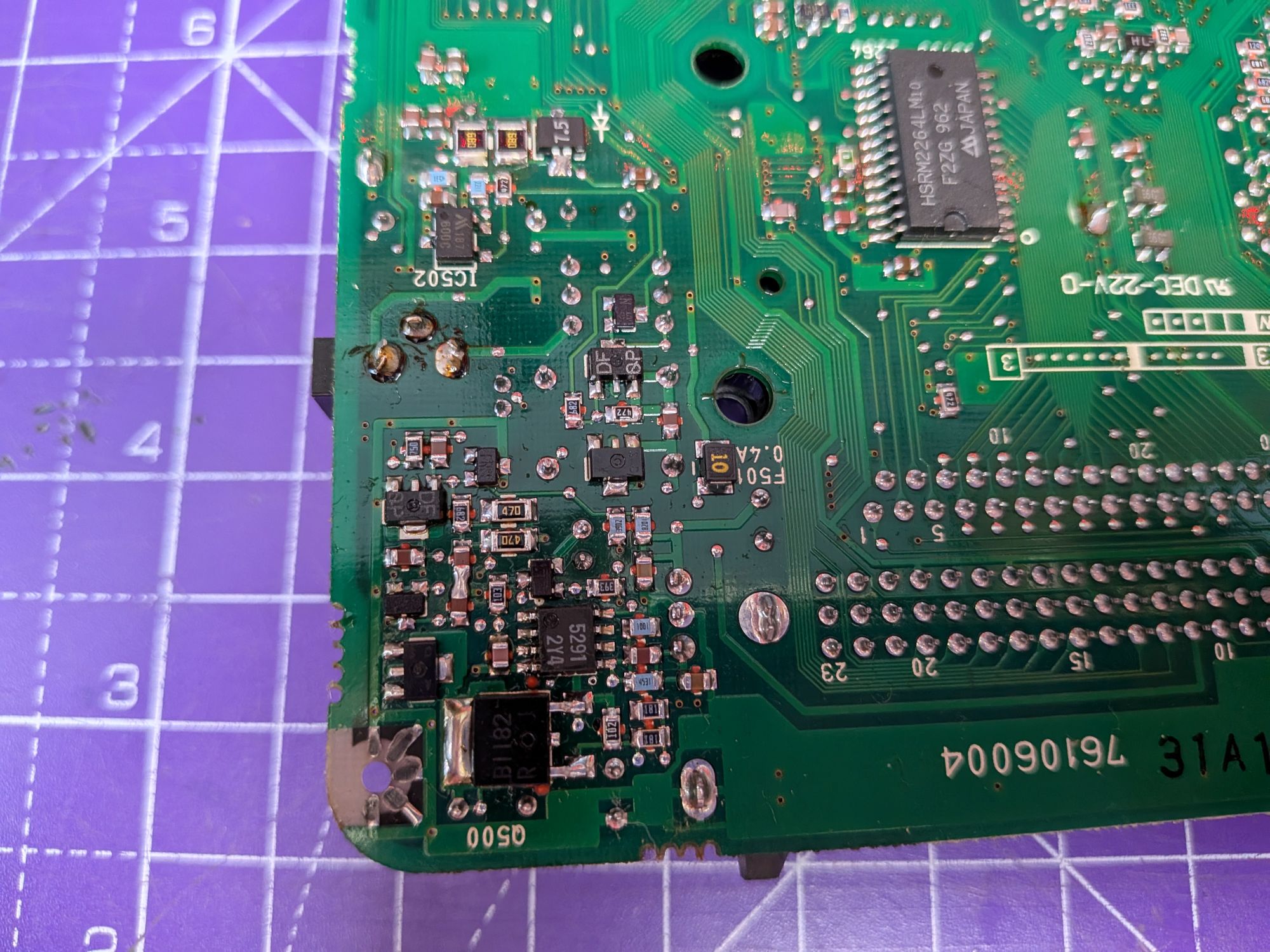
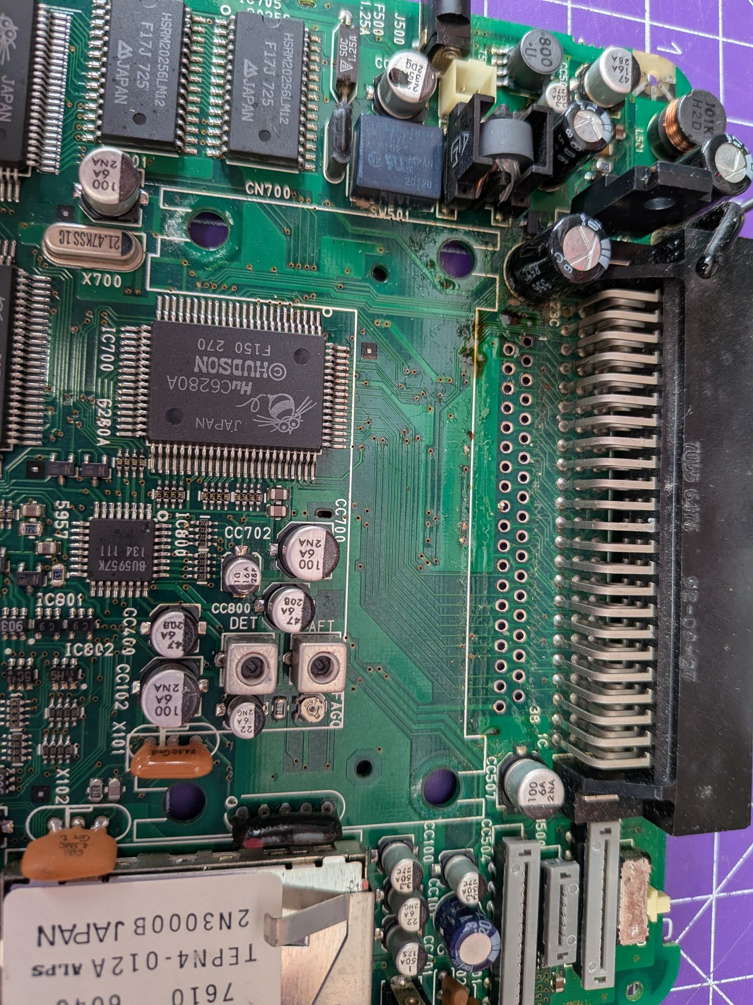
The pictures show the top and bottom of the board itself and a closer look at the power supply circuitry. A common failure point and likely to blame for this one currently presenting as dead.
The final pic above shows the top of the board, above the power supply area, with leaked electrolyte surrounding the capacitors and spread far and wide. Not good.
On to the recap.
The capacitors are grouped into 5 main areas. There’s a group in the corner where the power supply section lives, a section in the centre, one in the top right corner where the ribbons connect and one either corner at the bottom edge of the board. They’re mainly SMD electrolytic, which always seem to leak from this era. There are a few radial through hole too though.
Given how badly these appear to have leaked in the power supply it is likely all underneath the larger components there too. After consulting the owner it was decided to remove, at least, the card slot, the external bus connector and a large coil and relay to properly clean the board beneath them.
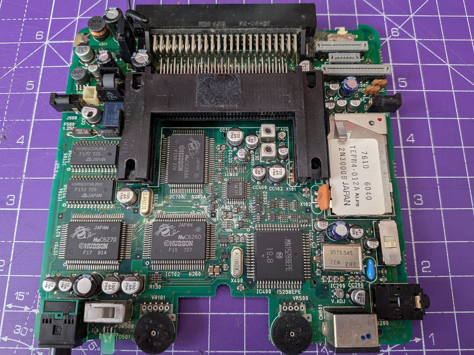
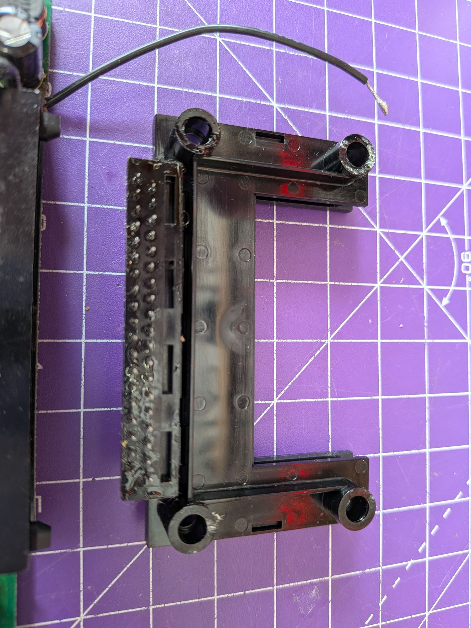
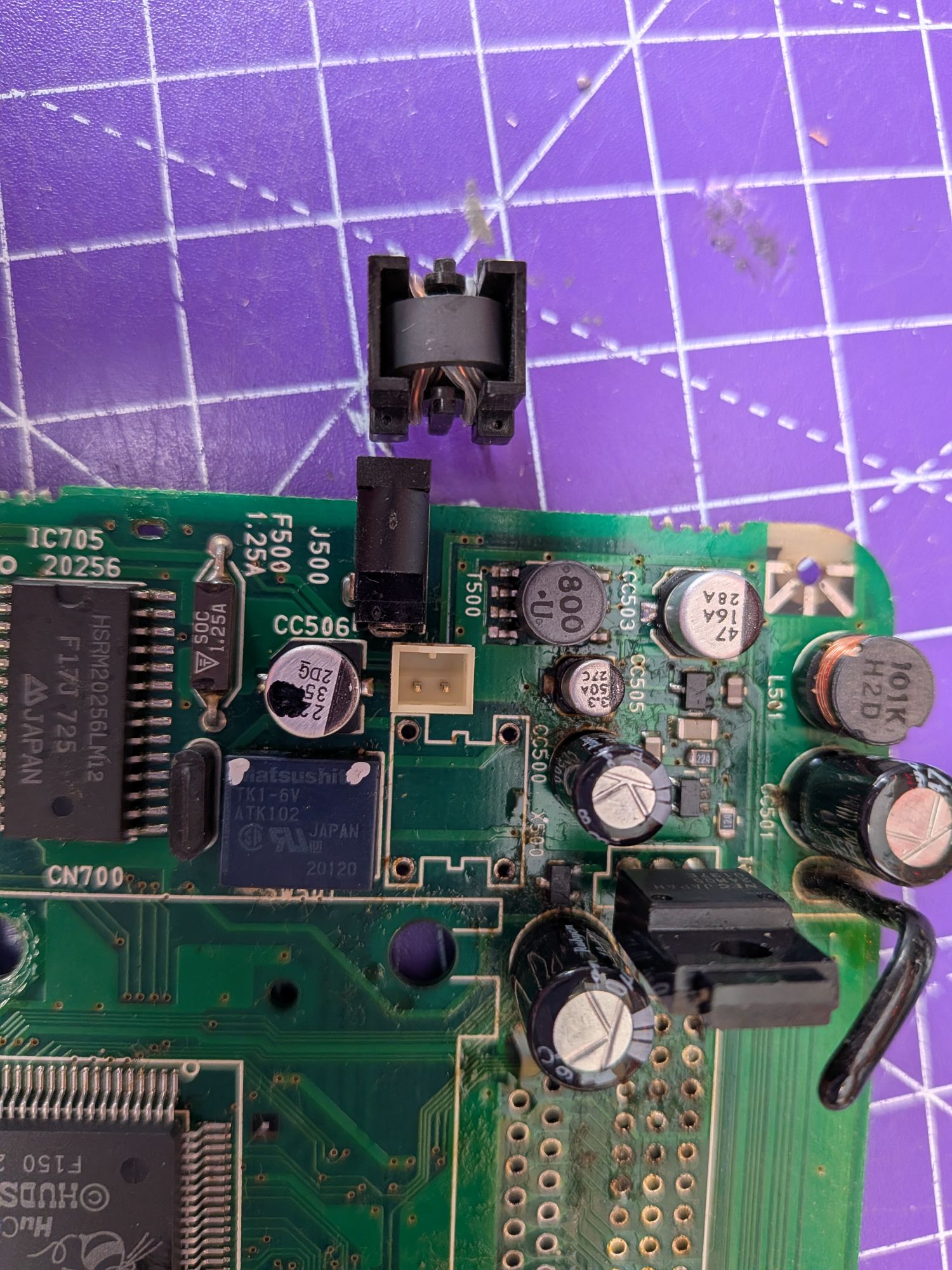
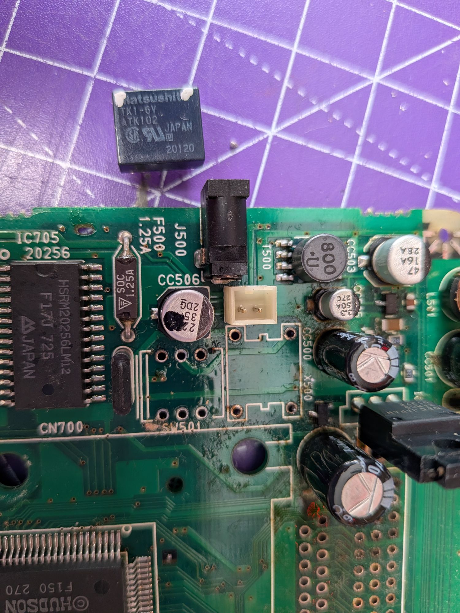
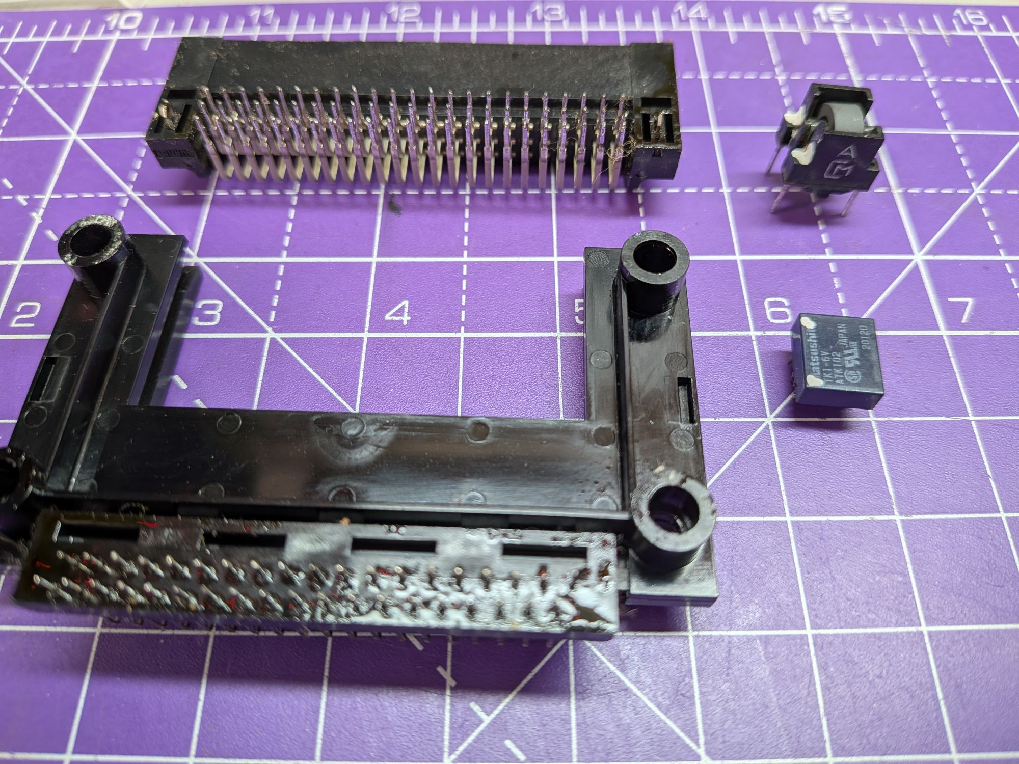
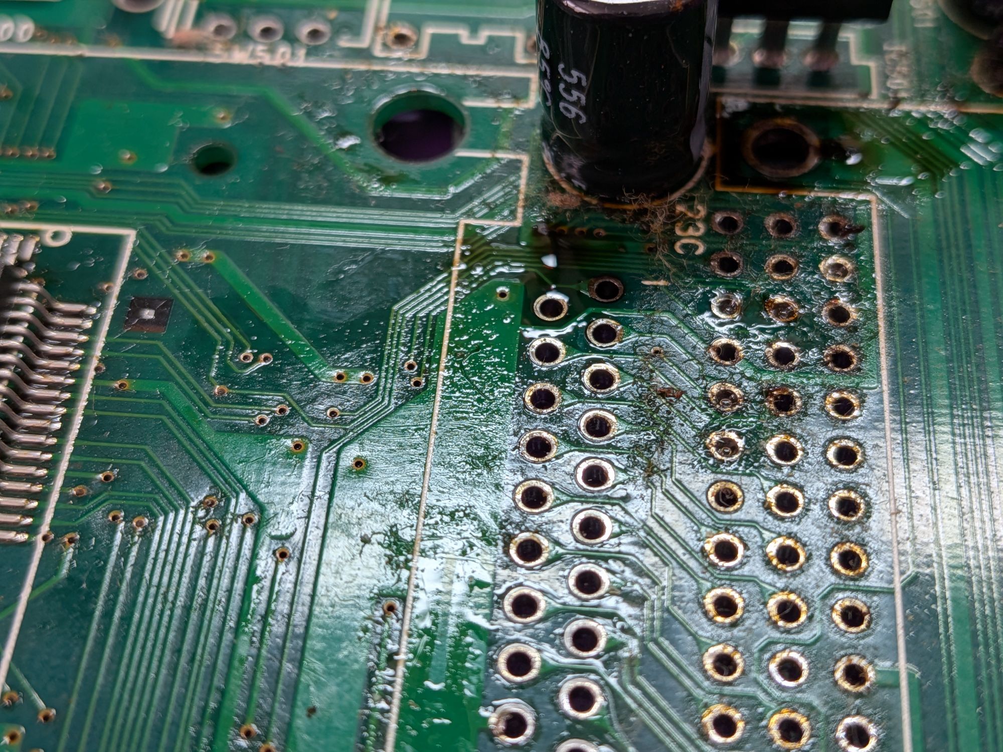
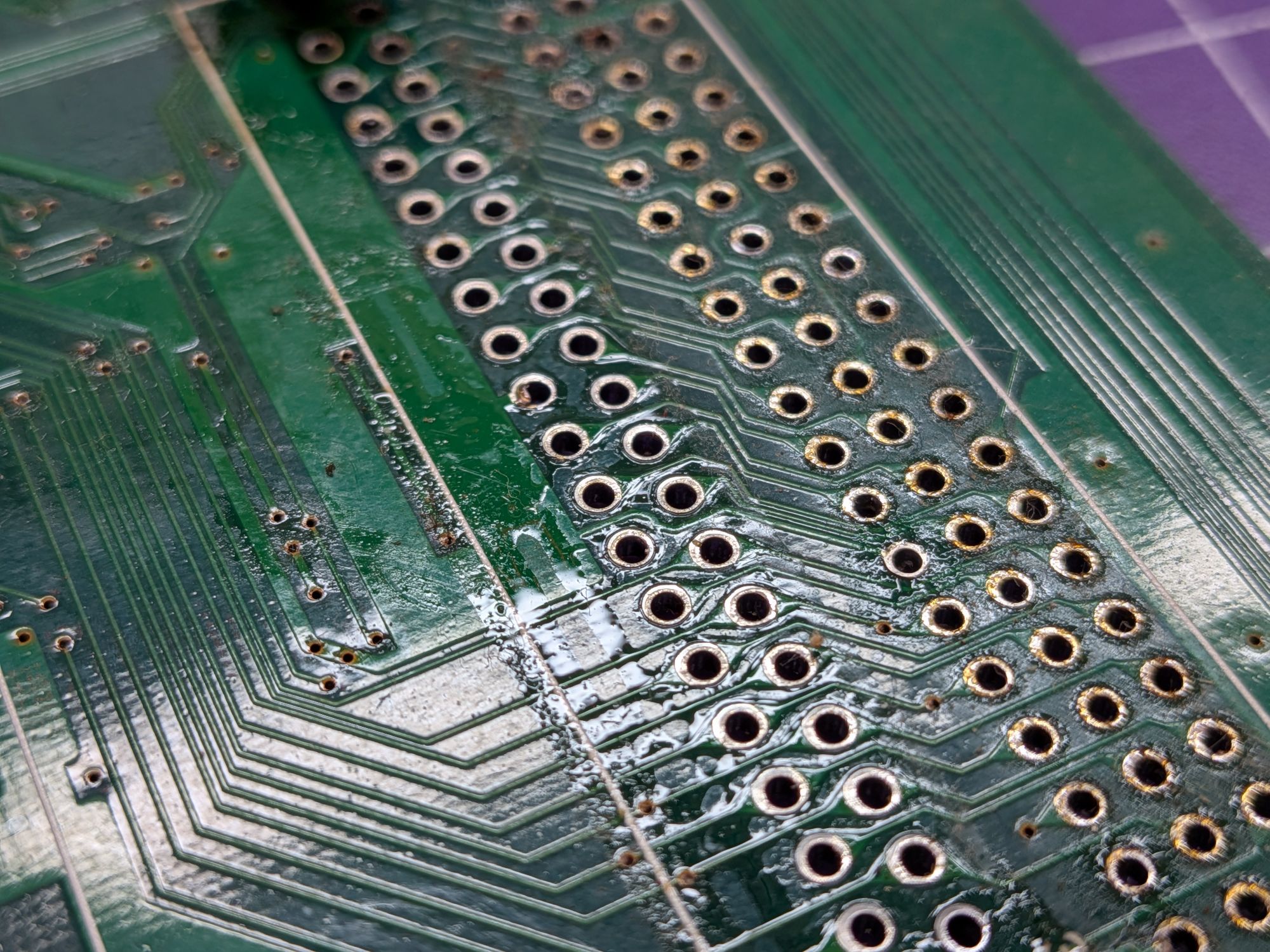
With everything removed, it’s a good job we did. The corrosive electrolyte from the capacitors was pooling underneath the large flat components. Over time, it would have corroded the copper traces of the board, destroyed the card slot and connector and essentially killed the system. The components themselves can also be cleaned with them now off the board.
This is a multi layer board. I think at least 4 layers. Top, two in the middle and bottom. It is incredibly cramped to work on, with components not in accessible places and not oriented in friendly way to be able to remove them. It’s not just awkward to access SMD components but being multi-layered makes the through hole ones difficult to remove too, and to clear the holes.
The internal layers disperse the heat so you tend to find either side is clear but the middle is still blocked. It’s not the kind of board you want to apply excess heat to either. Everything there is over 30 years old now and not necessarily able to handle it. No hot air or board heaters etc. It’s best to keep the heat very localised. Ideally quick and powerful heat, without being at a high temperature which can lift pads and cause further damage. This one convinced me to buy a new tool I had been trying to justify for some time now.
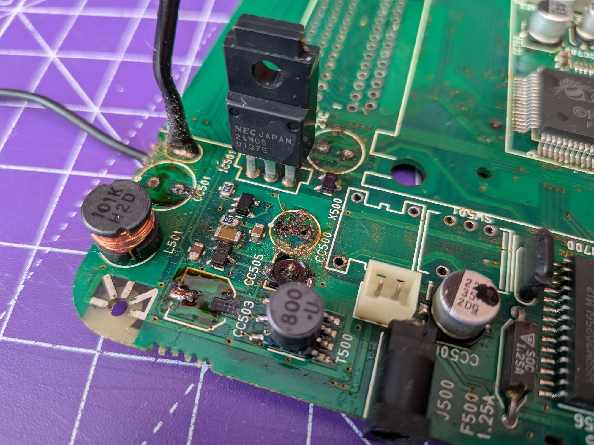
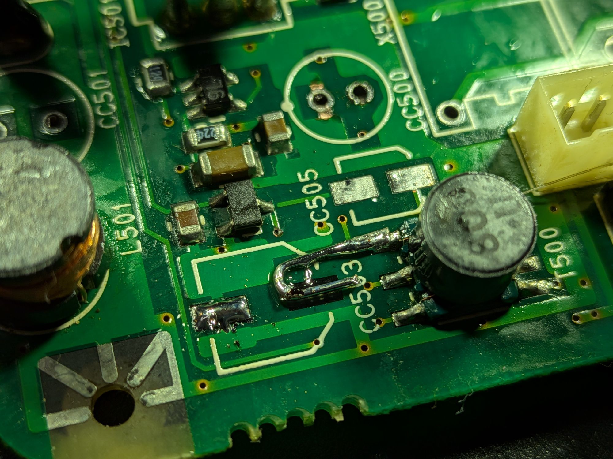
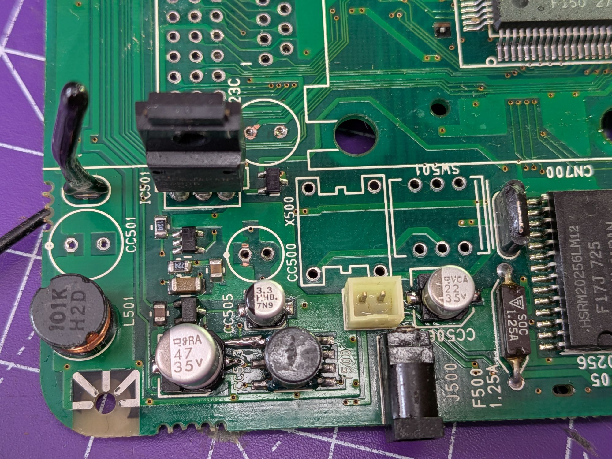
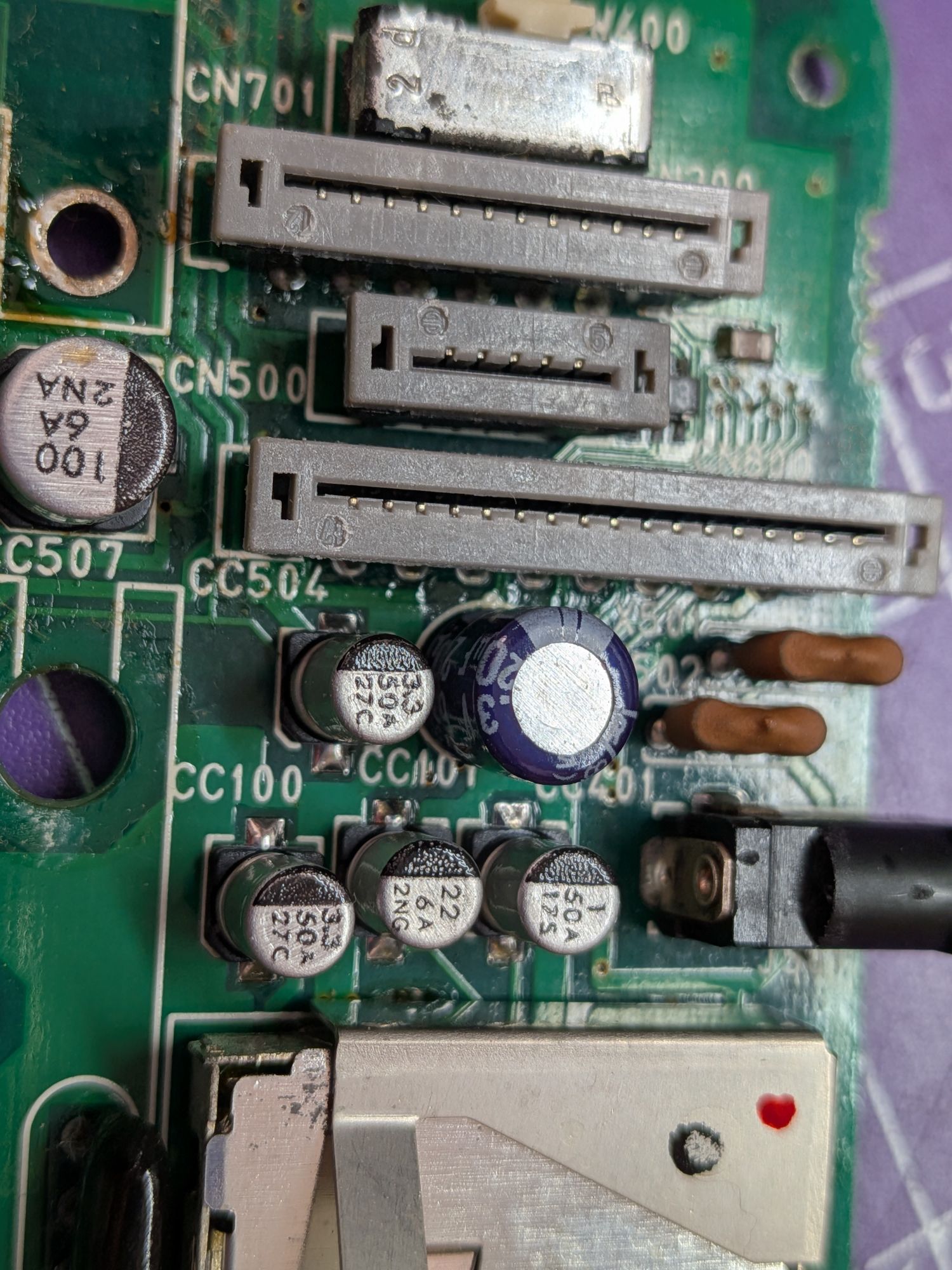
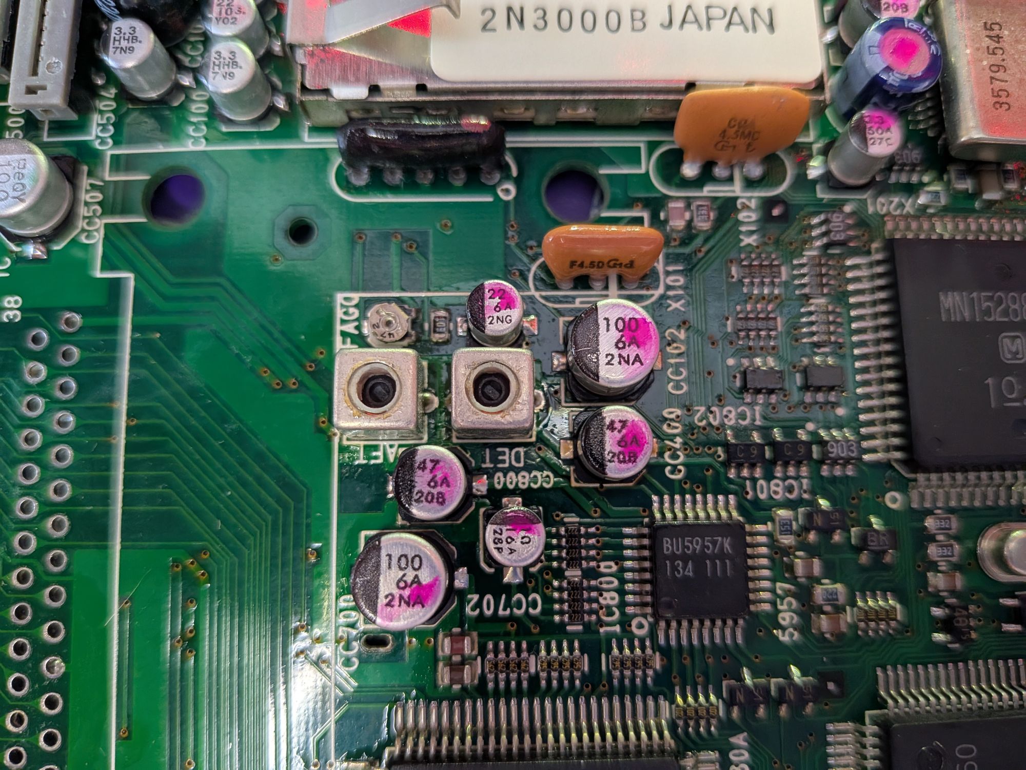
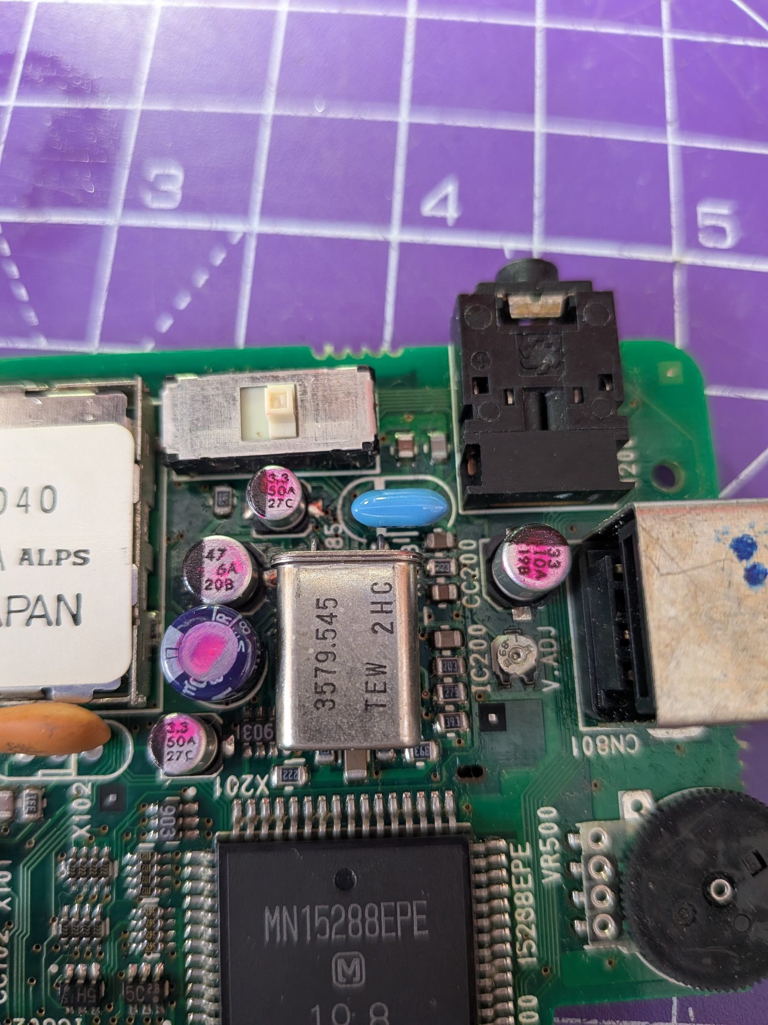
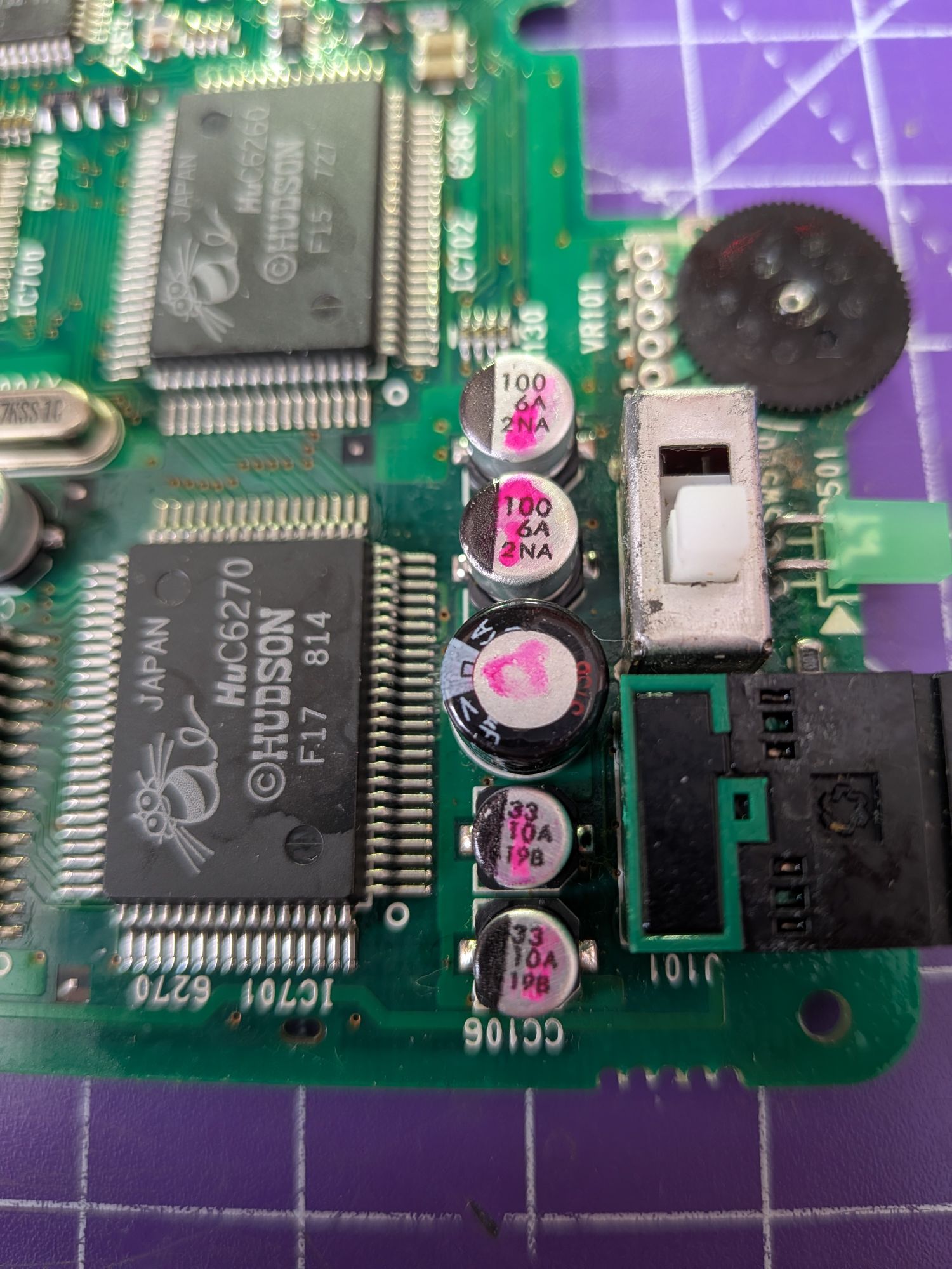
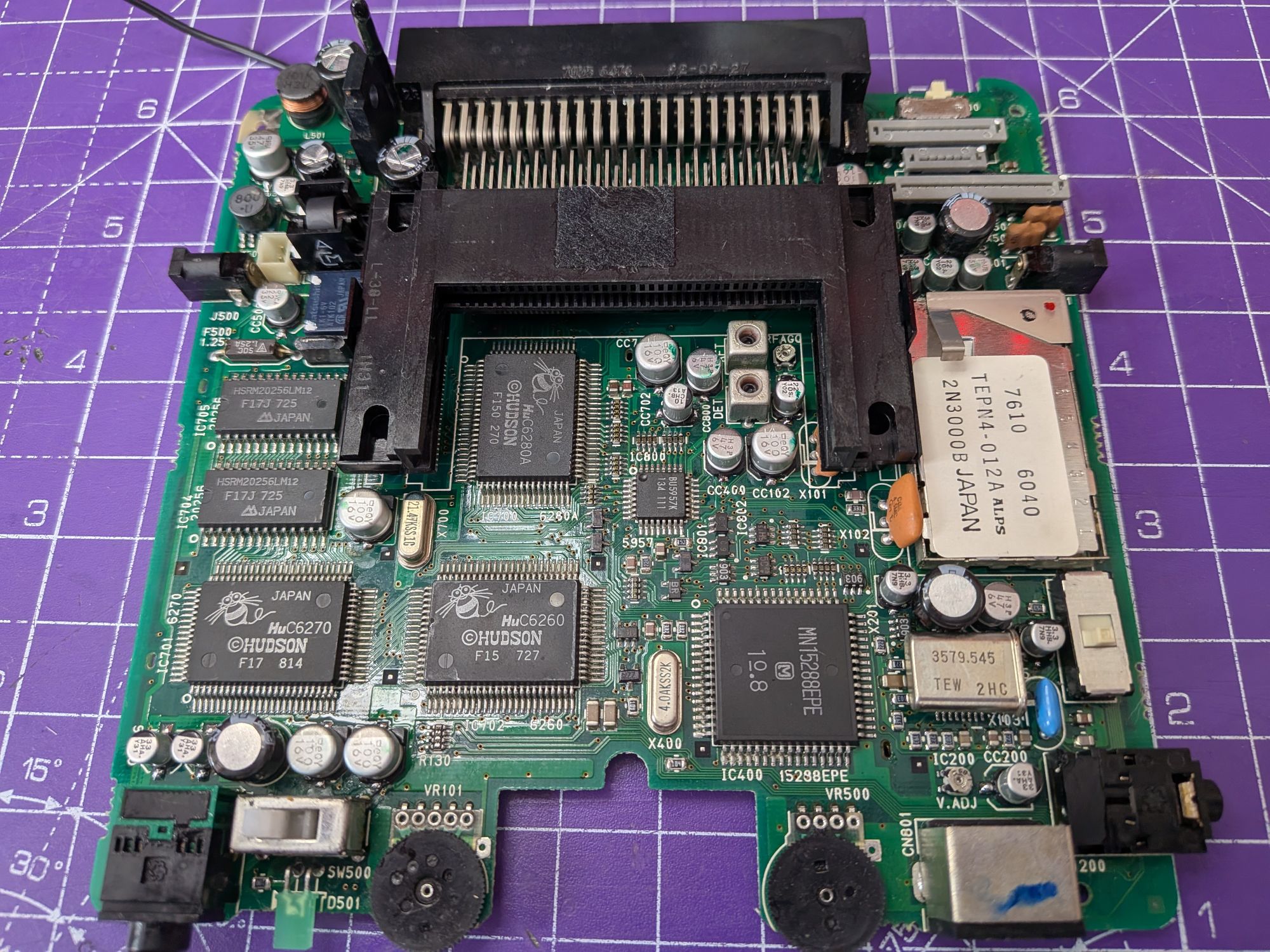
Leakage and corrosion underneath the capacitors, as you can see. It’s a bit of a mess but the actual corrosion is not too bad. One pad lifted in the power supply section, from the leakage getting underneath it. Used a cut-off component leg to replace it with and soldered the new capacitor to the leg.
There is leakage across the board but the power supply section was by far the worst. The ribbon connector area caused some concern too. I was considering removing the ribbon connectors to clean but decided not to in the end. There’s a risk of deforming the spring terminals with the heat and also melting the plastic package. It can be difficult to find replacements for these now so thought it best to just flush thoroughly with IPA instead.
With everything replaced and the board thoroughly cleaned it was time for some testing and to put it all back together again.
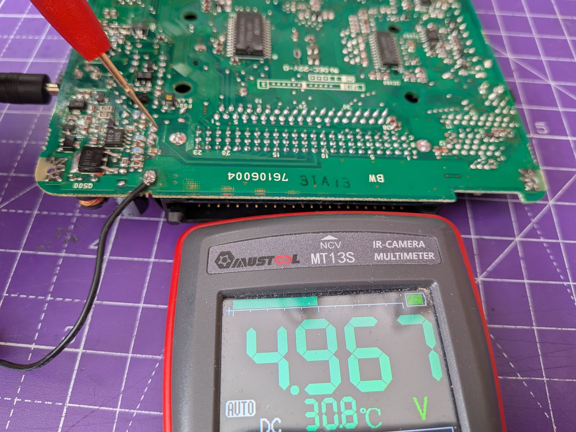
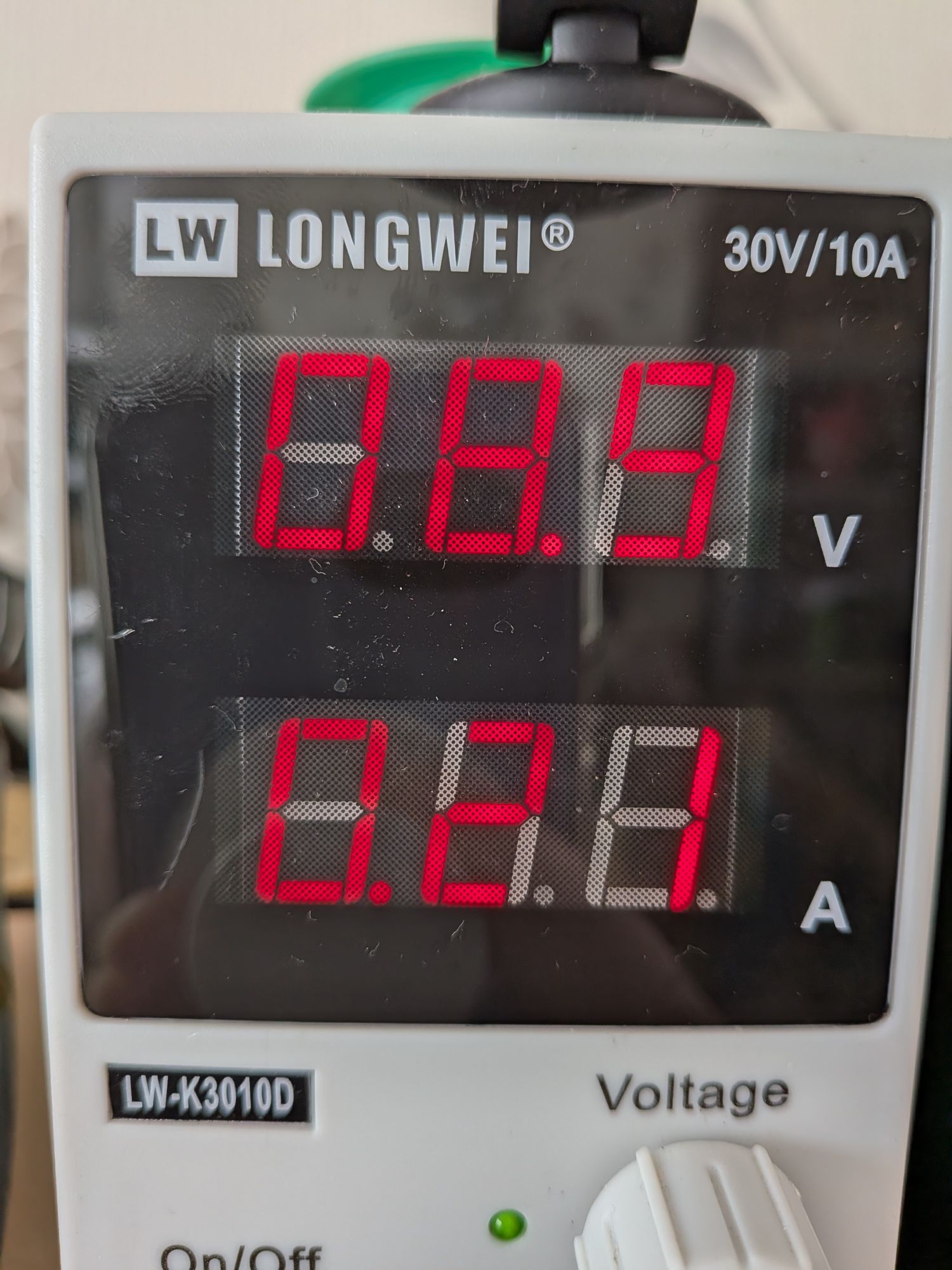
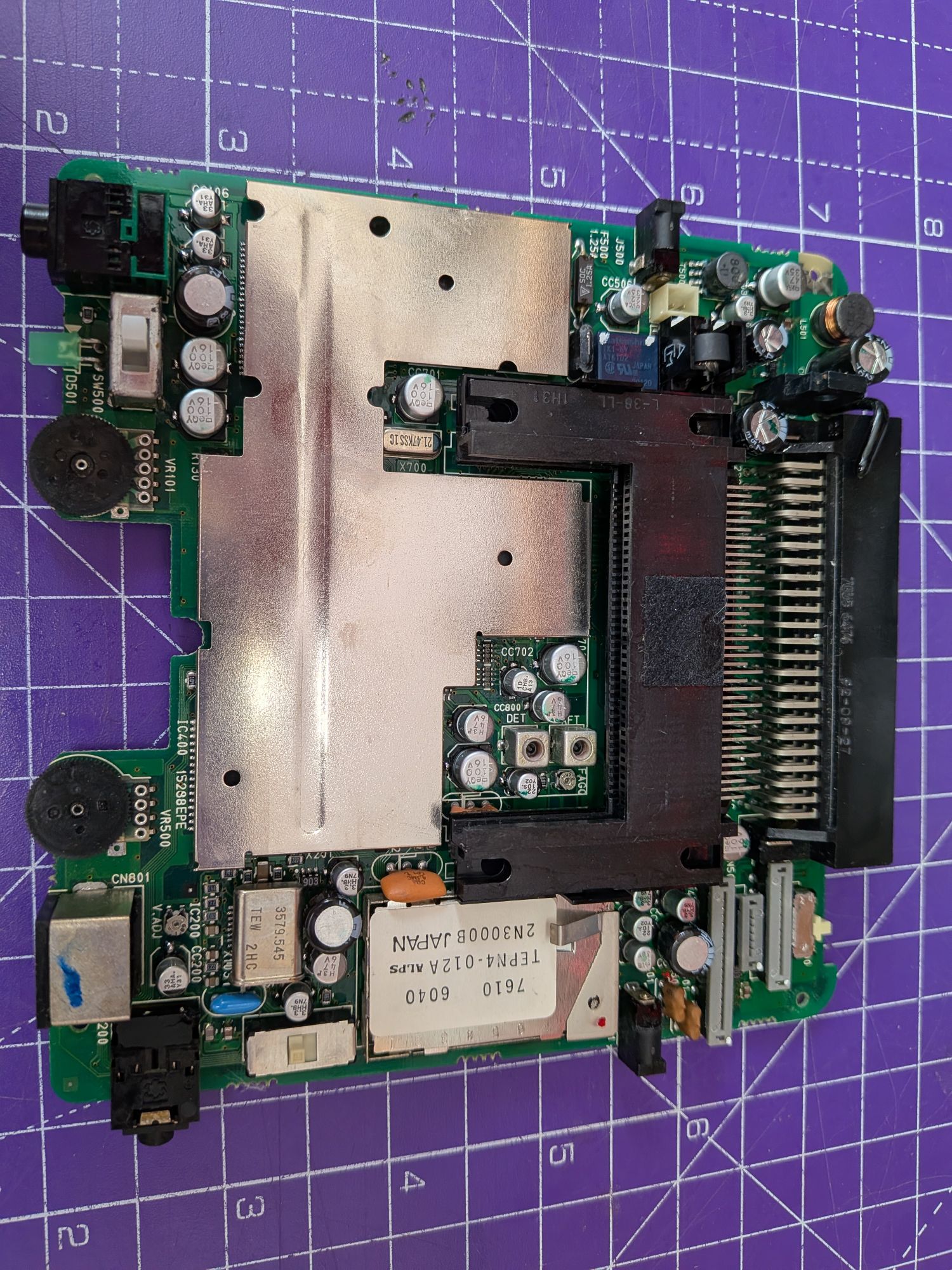
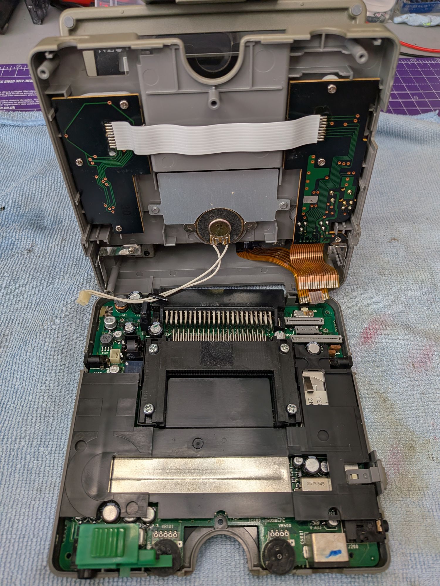
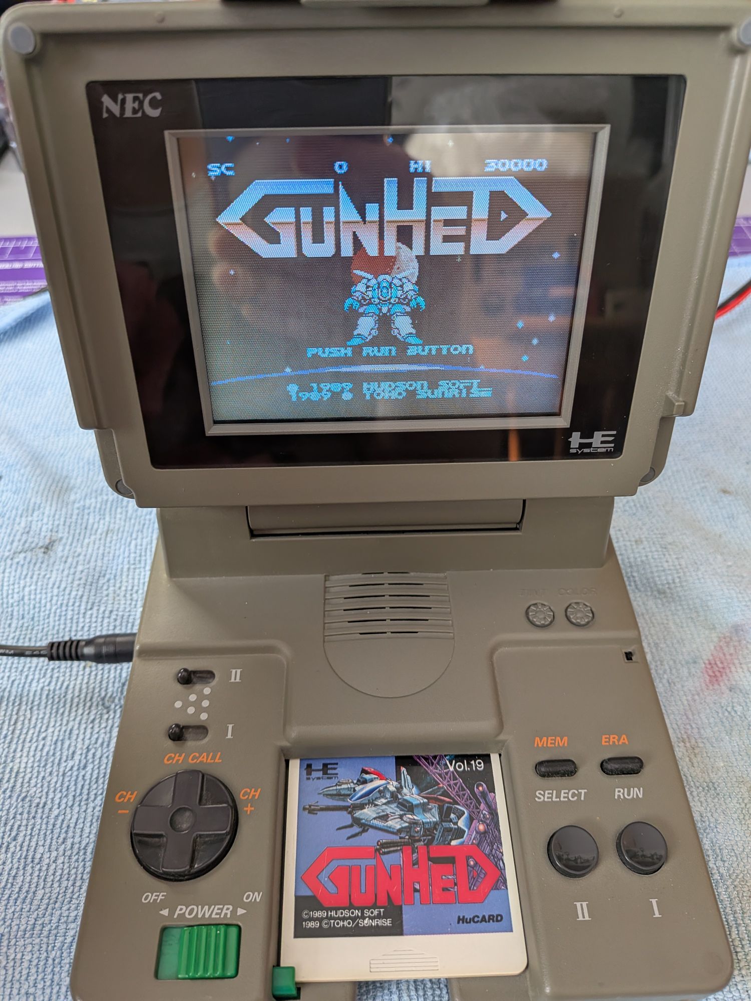
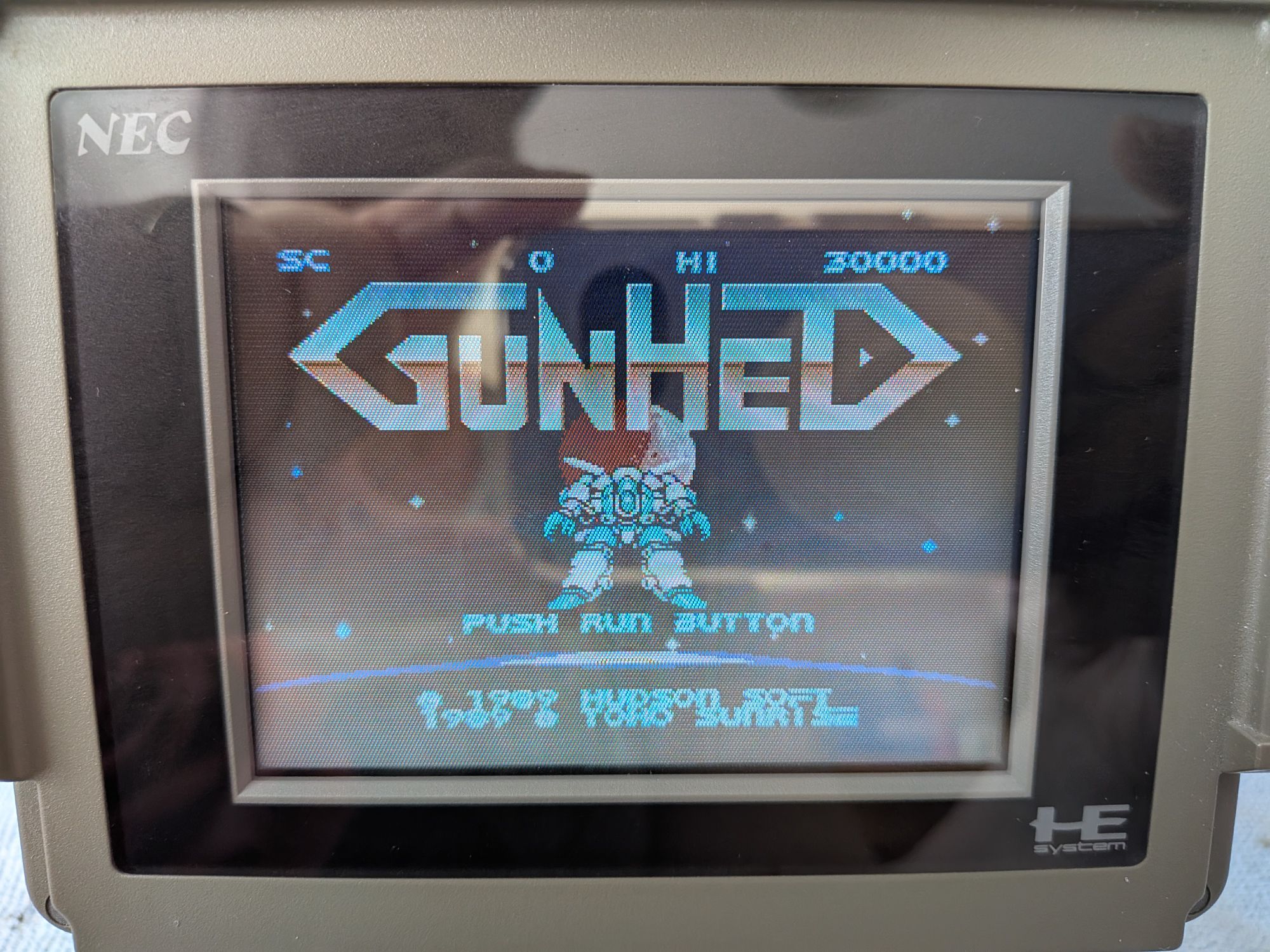
First thing to test was that the power supply was now outputting the correct voltage, now with the full input voltage. It should be at 5V, so that’s pretty good, isn’t it. The current draw seemed normal too.
Not shown here but I also tried it with headphones plugged in to check there was sound output from a game. We now know it’s back up and running and can start to put it all back together!
Those ribbons are incredibly short. It is a proper pain to get them all plugged in. There’s very little room there, it’s tucked in an inaccessible corner, like everything else, and there are 3 really close together.
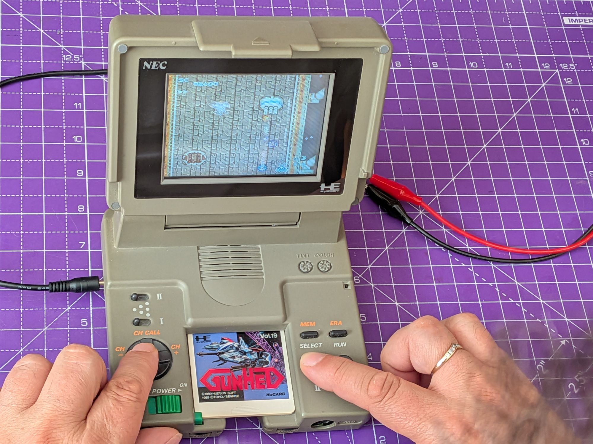
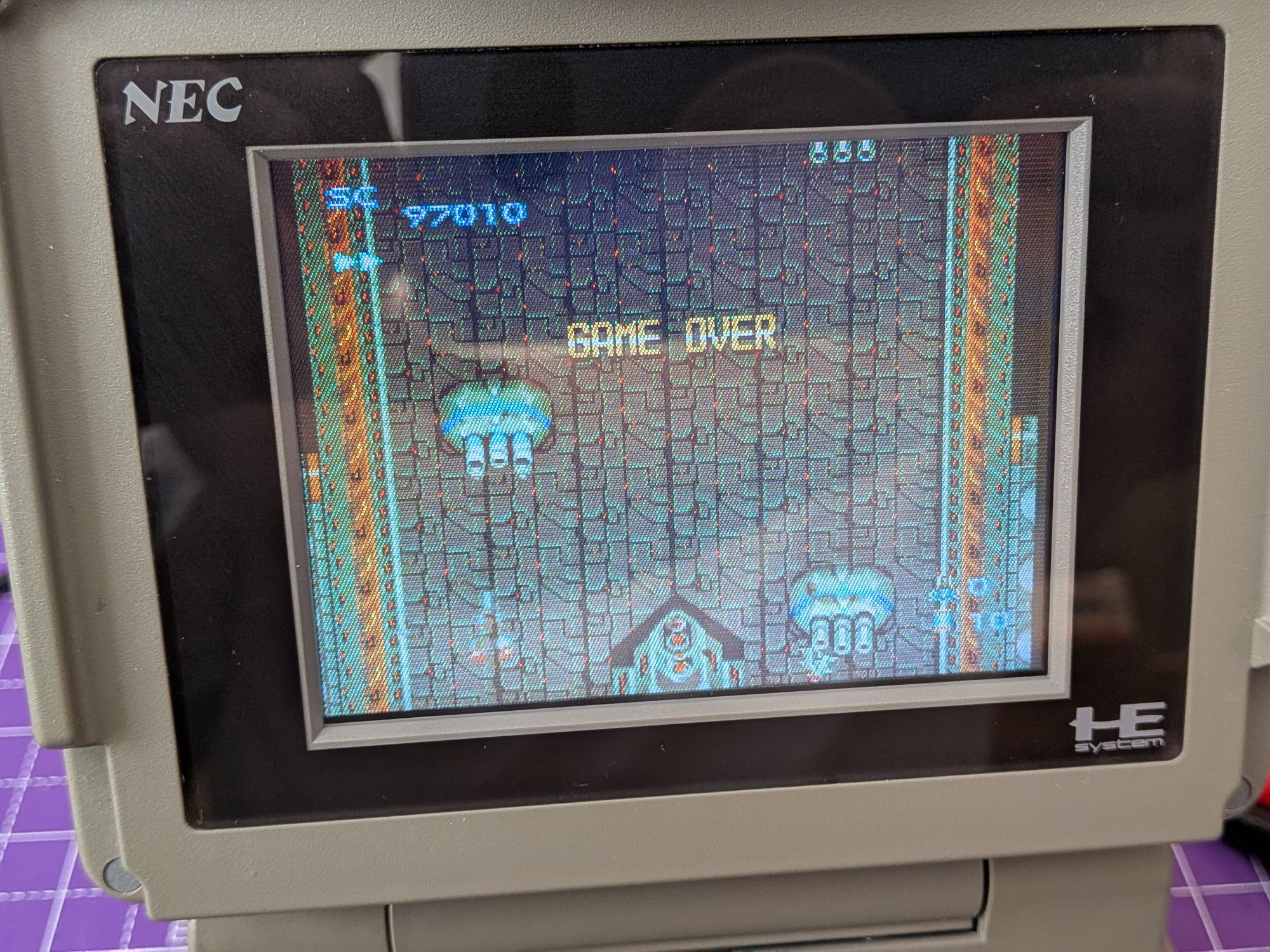
Finally time to test it! The screen is pretty decent. Bright and colourful. This is an impressive little system.
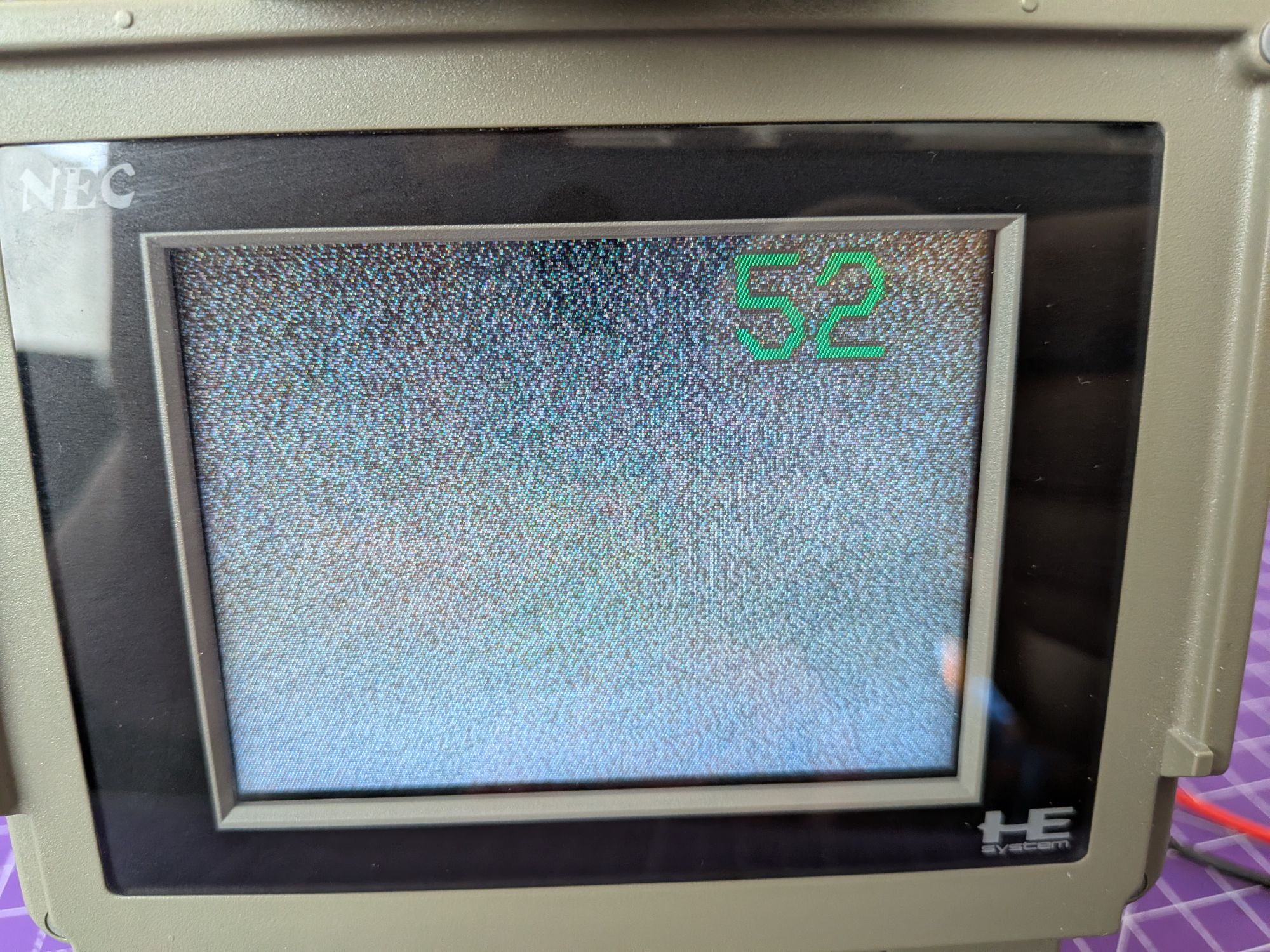
Extending the surprisingly long aerial and switching the switch to TV, it showed snow and channel number too. Went through the preset channels and switched it to tuning mode at the back to scan through the TV frequencies. All good here.
Sooo time to enlist some help with the testing!
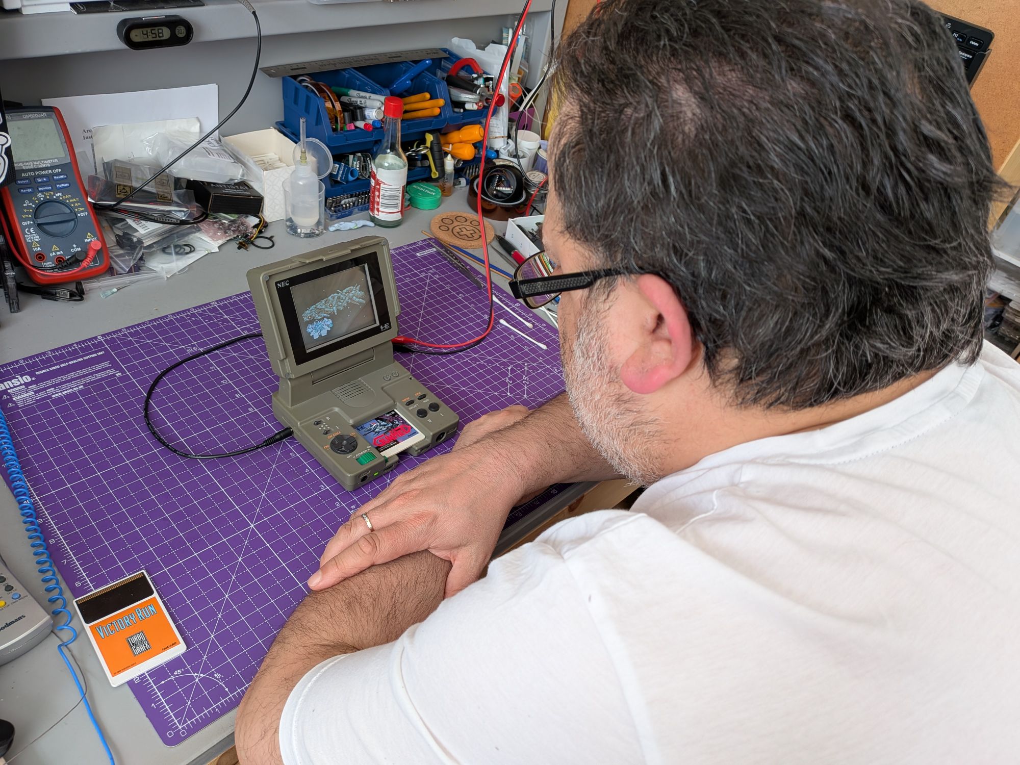
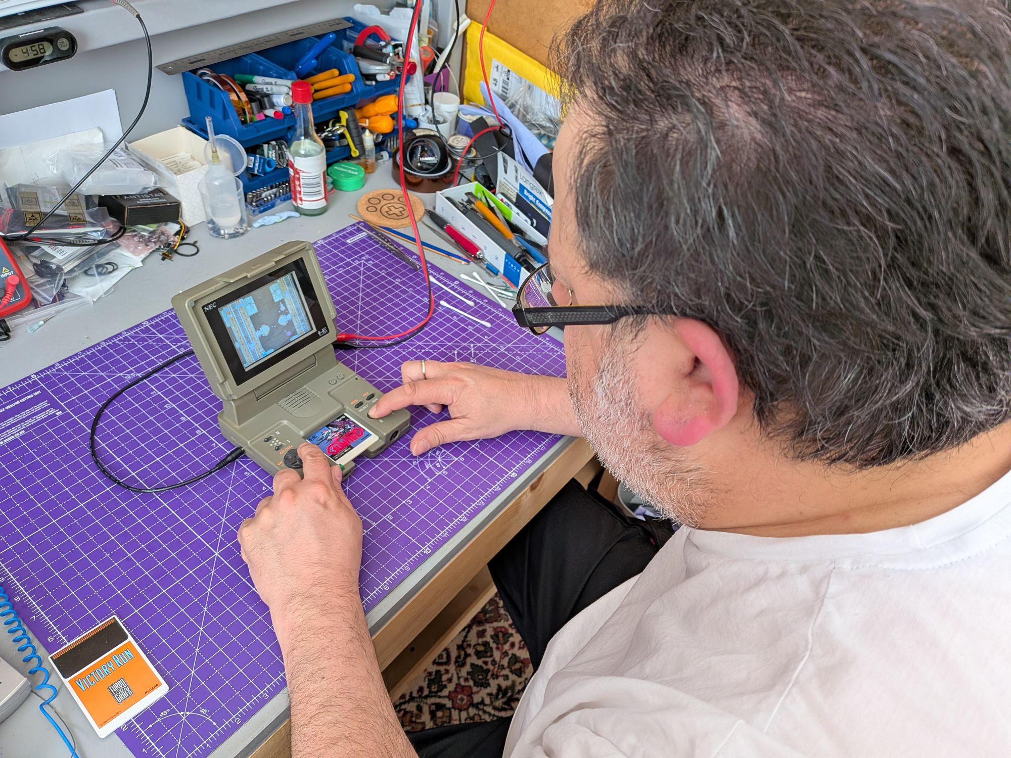
One Response