


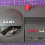
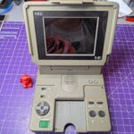
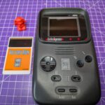
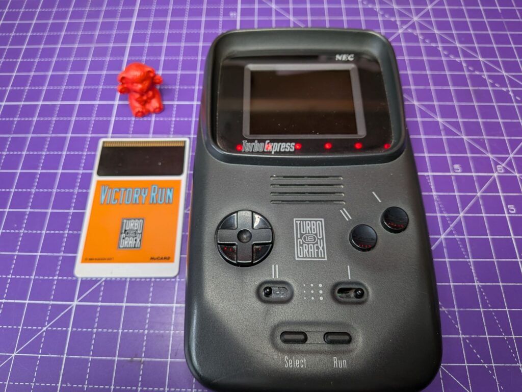
Something fancy today! Fun fact: This is the console they’re searching for in the top 90s movie Enemy of the State, with Will Smith.
Lots of pictures, bear with.
This one has been languishing in the repair queue, along with its even fancier cousin, as I needed to allot more time to the two of them than I had available. It is quieter than usual at the moment, with many people away on holiday I suppose, so using the time to catch up with some more complex jobs while I can. As it turns out, this one at least, was in pretty good condition.
As with all PC Engine and TurboExpress consoles, they tend to suffer with aging and leaky capacitors. Not all consoles do by any means. These are notorious for it though. Leaked electrolyte is corrosive and over time can cause a lot of damage. On high density, multi-layer boards like this it can cause hidden damage too that can be a complete nightmare, both to find and to work around. It’s not something you want to do in a rush.
It’s a really nice handheld console which was ahead of its time in many ways. When you think, this was released around the same time as the original Game Boy. It’s amazing really.
Let’s have a good look around this wondrous thing..
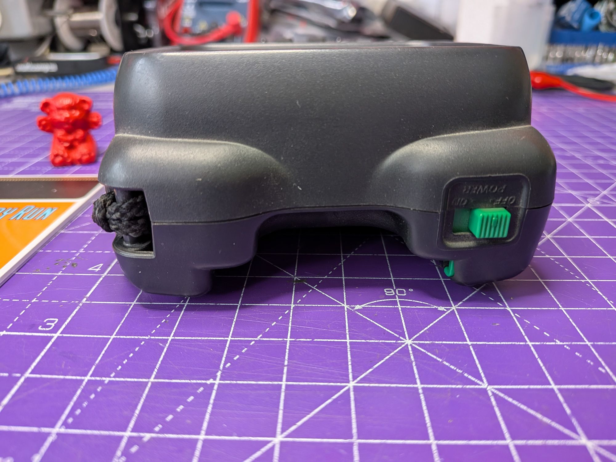
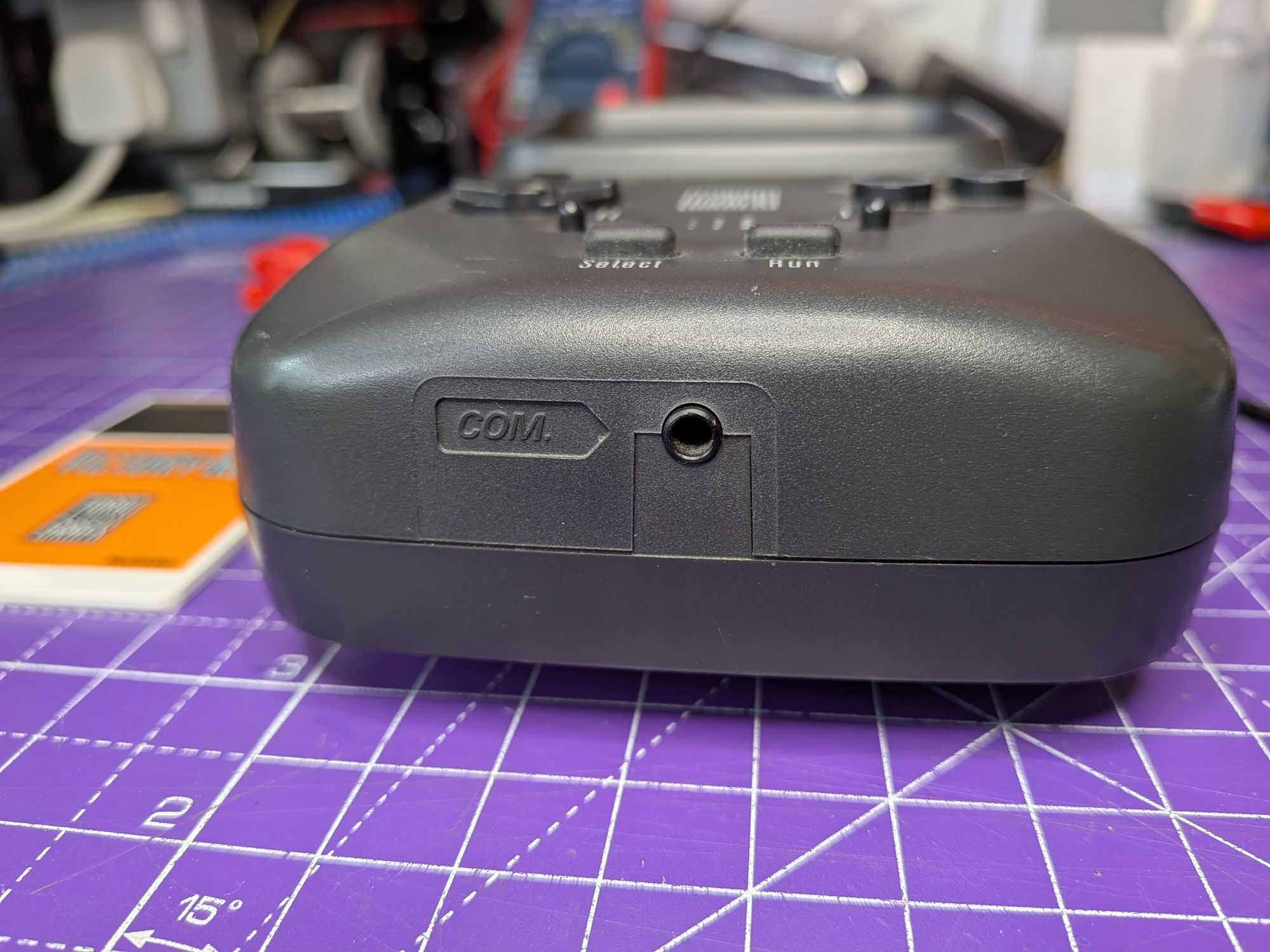
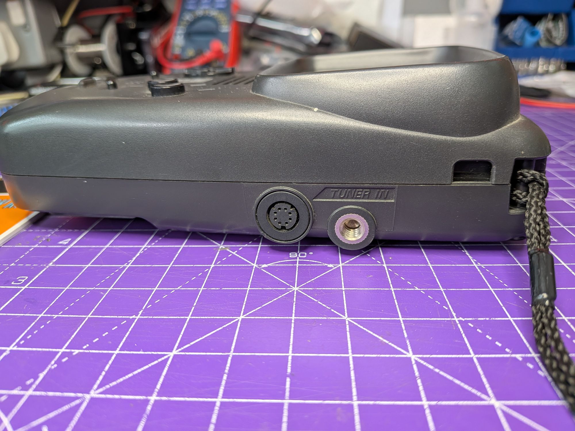
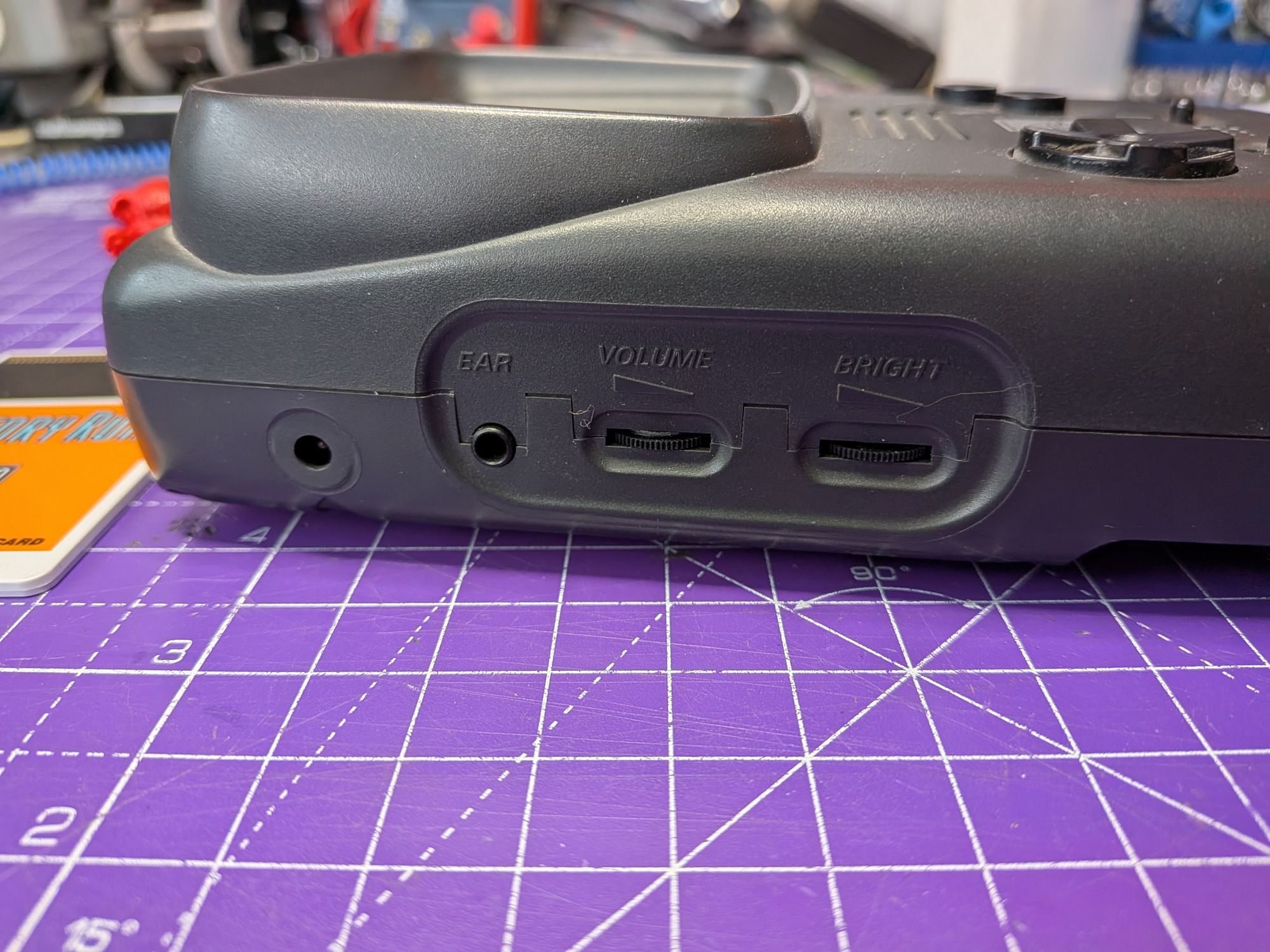
It’s chunky, isn’t it but it feels good in the hands. The COM, I believe is for a link cable, if you happen to have two of them, and a link cable. The Tuner was an analogue TV tuner that plugged into the side. Not so useful nowadays but pure magic in the 1990s. Standard fair with the power etc.
It uses the same size plug as the Lynx and a few others, a 3.5mm x 1.35mm one. It is centre positive but at a slightly strange voltage of 7V. I mainly use a bench power supply anyway, which helps with diagnosing things but have, until now, never felt the need to get such a plug. I tend to build sets of plugs with tails that I can connect a bench supply to, in whichever orientation. I’ve always managed without one of these but have now bought 3 of them, preassembled, for under £5 🙄
These are power hungry beasts and will likely drain a set of batteries in 3 or 4 hours. In reality though you’re likely to give up on it long before that and replace them.
I fitted some for a quick test and measured 8V across the 6 batteries, which is down from 9V or so as-new batteries but not terrible. It was enough for it but as it tried, and failed, to play sounds out of the speaker, the screen would white out, completely losing contrast. It really needs good batteries.
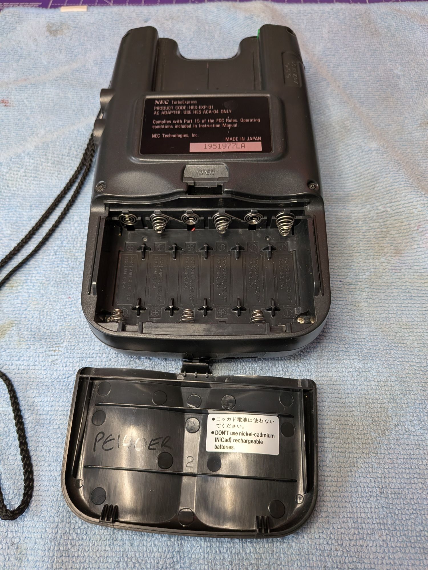
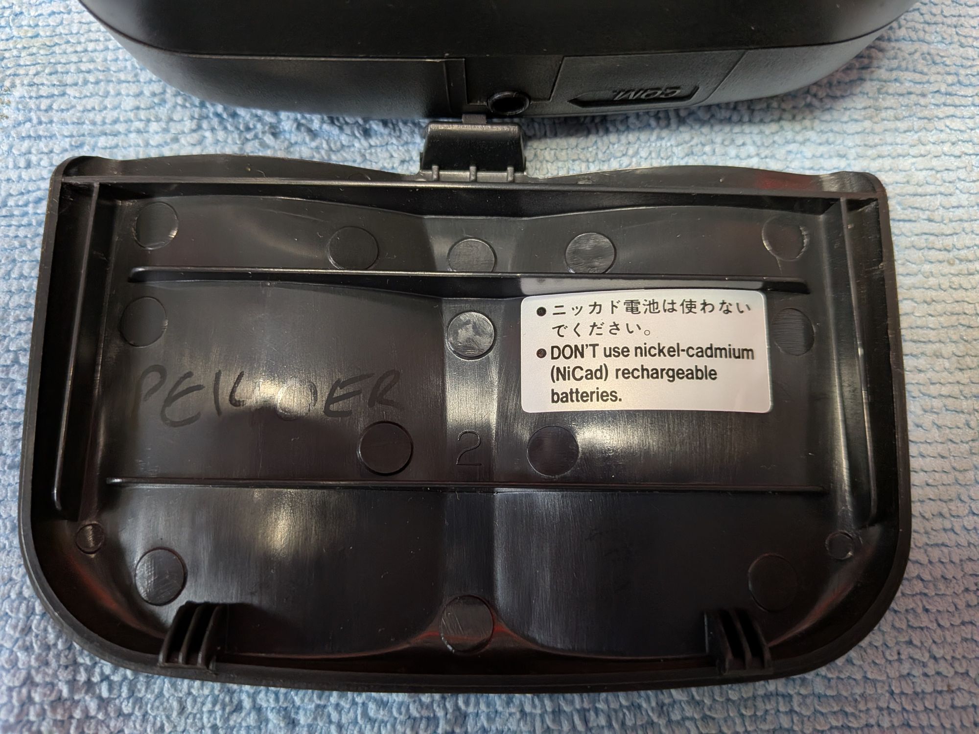
The warning sticker about using NiCad or rechargeable batteries is because they each output 1.2V when fully charged, rather than 1.5V of a regular battery, which across 6 batteries means it would be 7.2V at best.
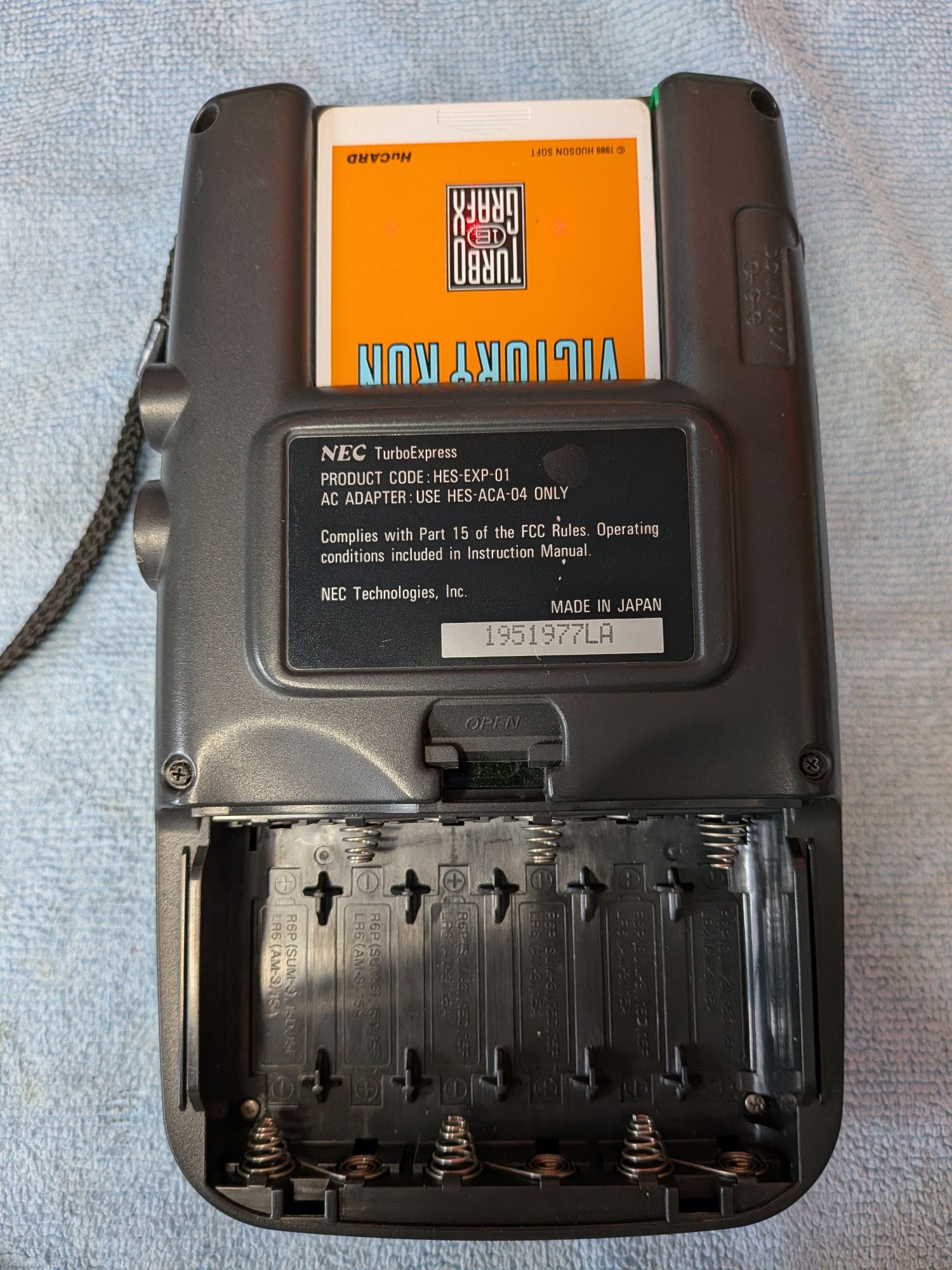
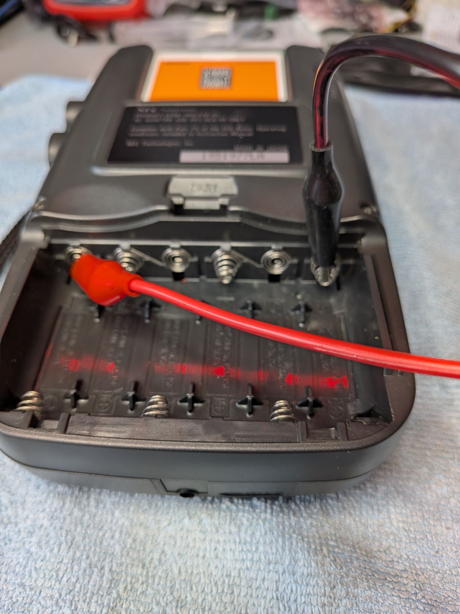
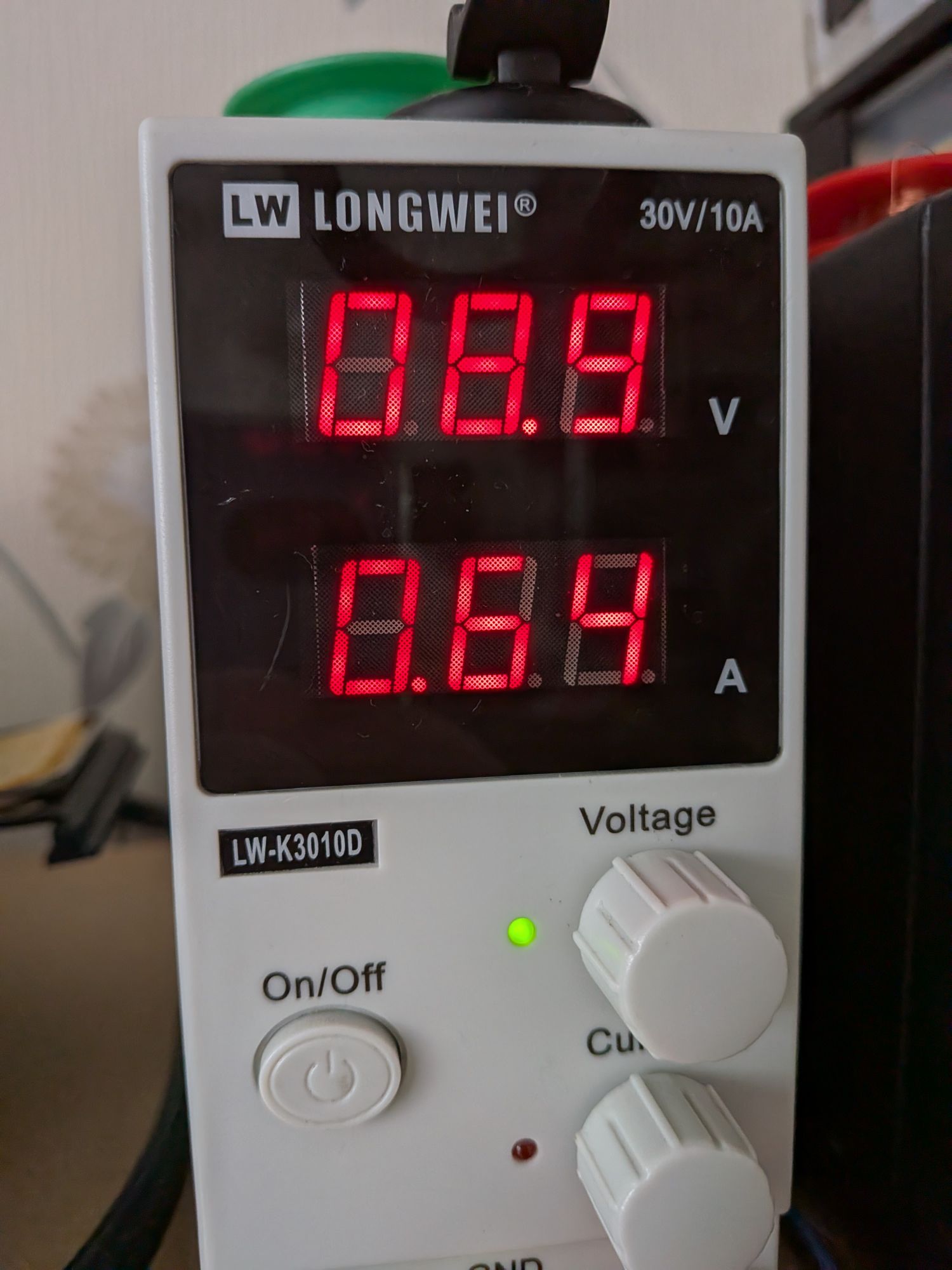
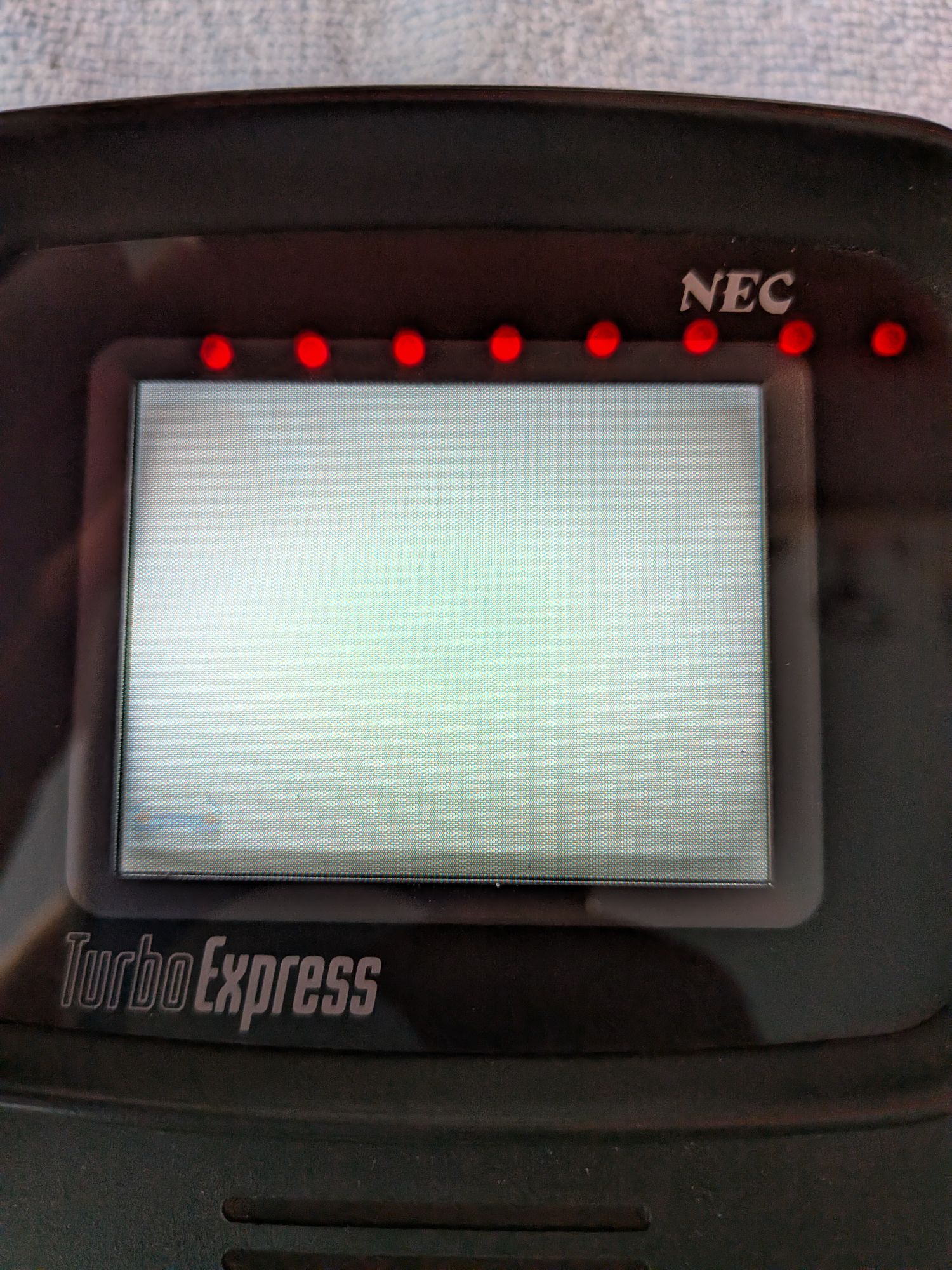
With a TurboGrafX card inserted – different from PC Engine – I connected with 9V directly to the battery terminals. Pre-recap it was drawing approximately 640mA, which is about equivalent to other consoles. It seems particularly sensitive to the voltage though.
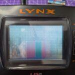
The game loaded, a driving game. You can just about make out a car and it seemed to move around. It’s very due a recap.
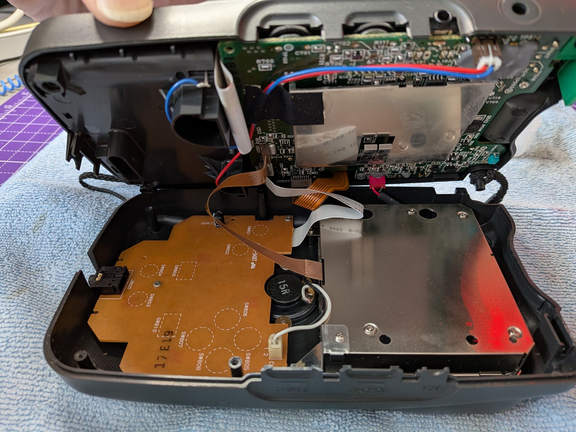
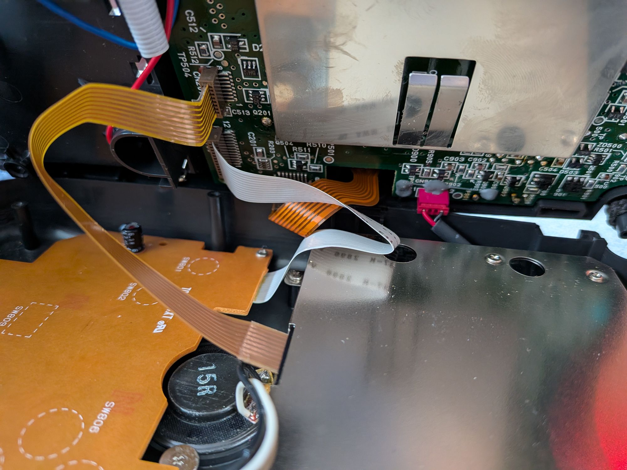
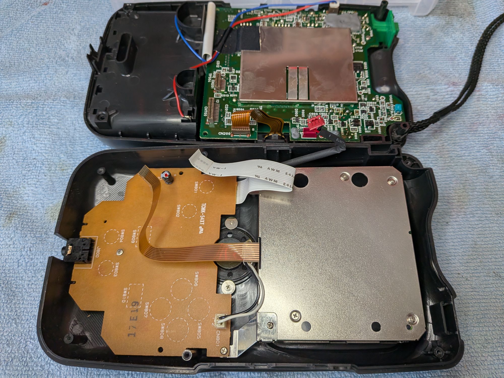
Making our way inside, there are six screws to undo on the back. Four long screws accessible from outside the case and two shorter ones inside the battery compartment.
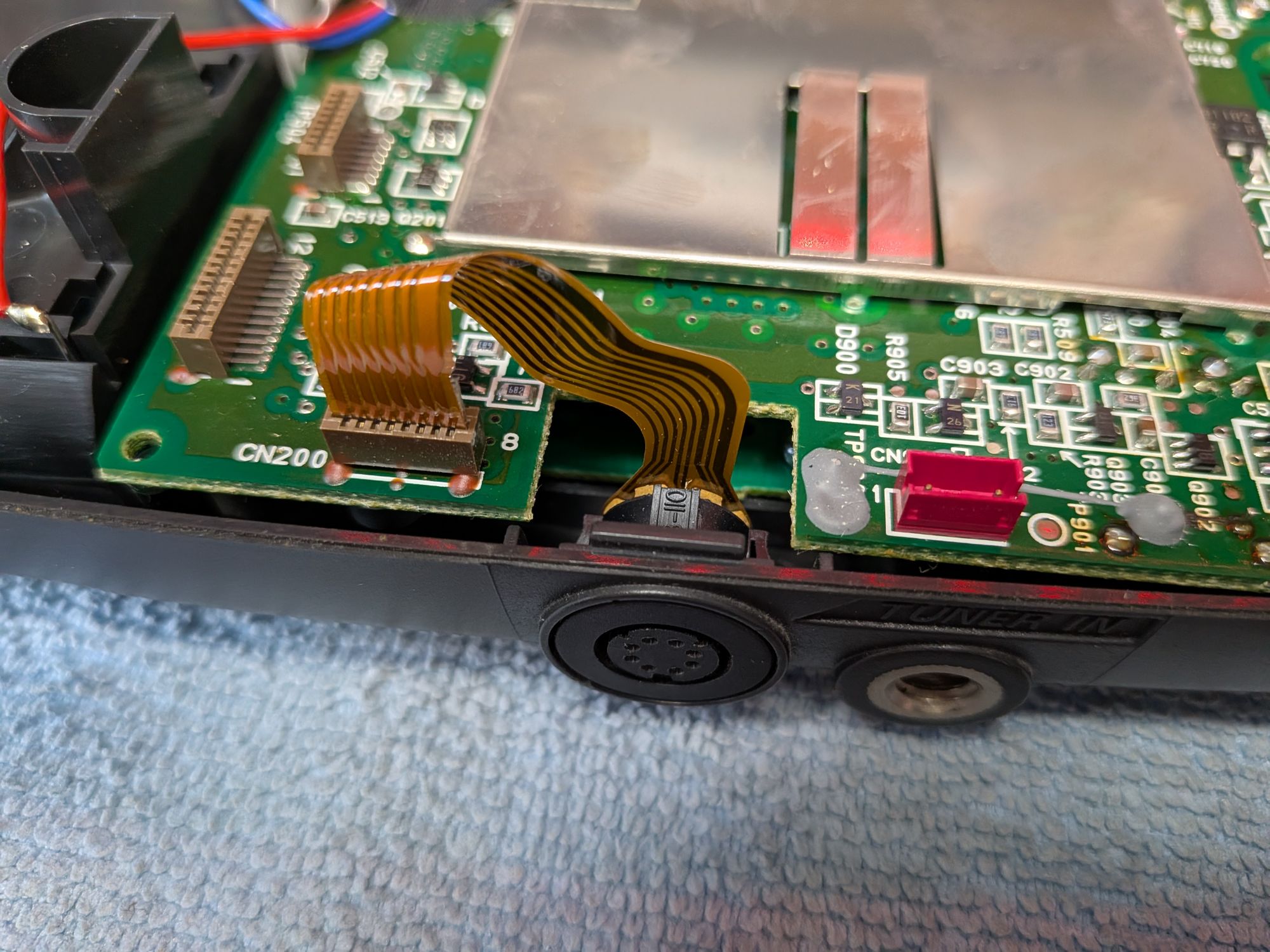
Opening gently from the left side where the volume and brightness wheels are, you can see there are ribbons to detach. Thoughtfully they are plenty long enough to do so but the red plug, I’m assuming that to be for the screen backlight, is a bit short and best tackled from the other side. The brown ribbon is the screen connection and the white ribbon is from the button board.
To remove the board there is one screw, towards the top and another ribbon cable to disconnect, going to the Tuner socket. It is quite short and a bit of a fiddle to get out. There’s not quite enough room to get your finger properly behind it to grip it well. It would be easy to tear this if it came out suddenly, so care is needed.
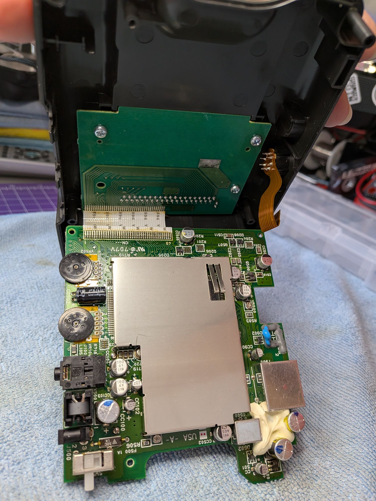
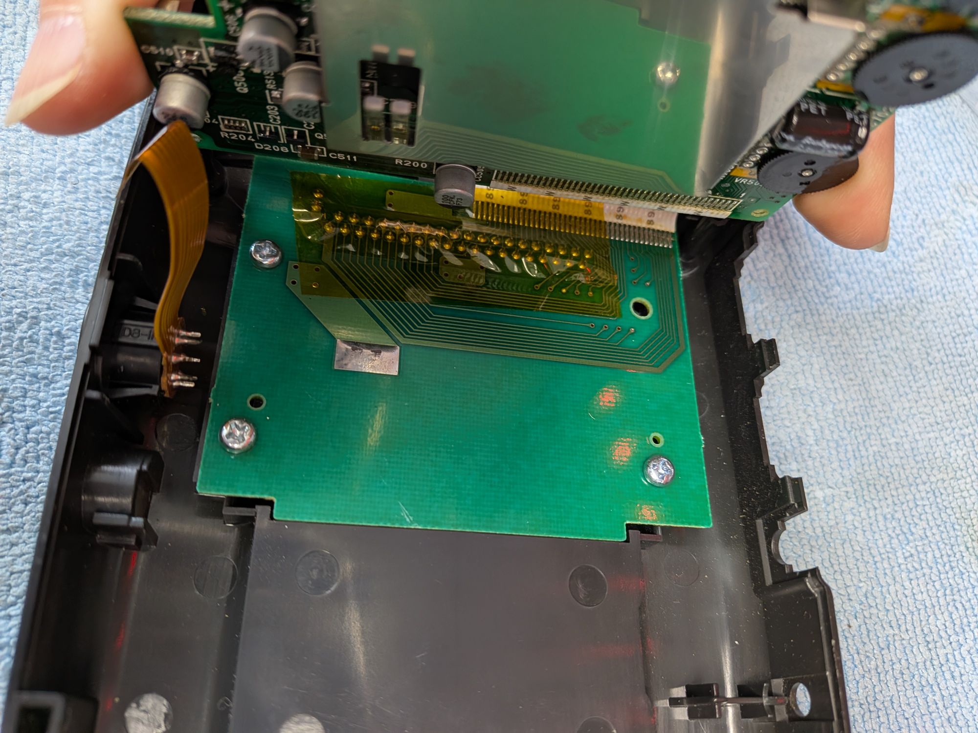
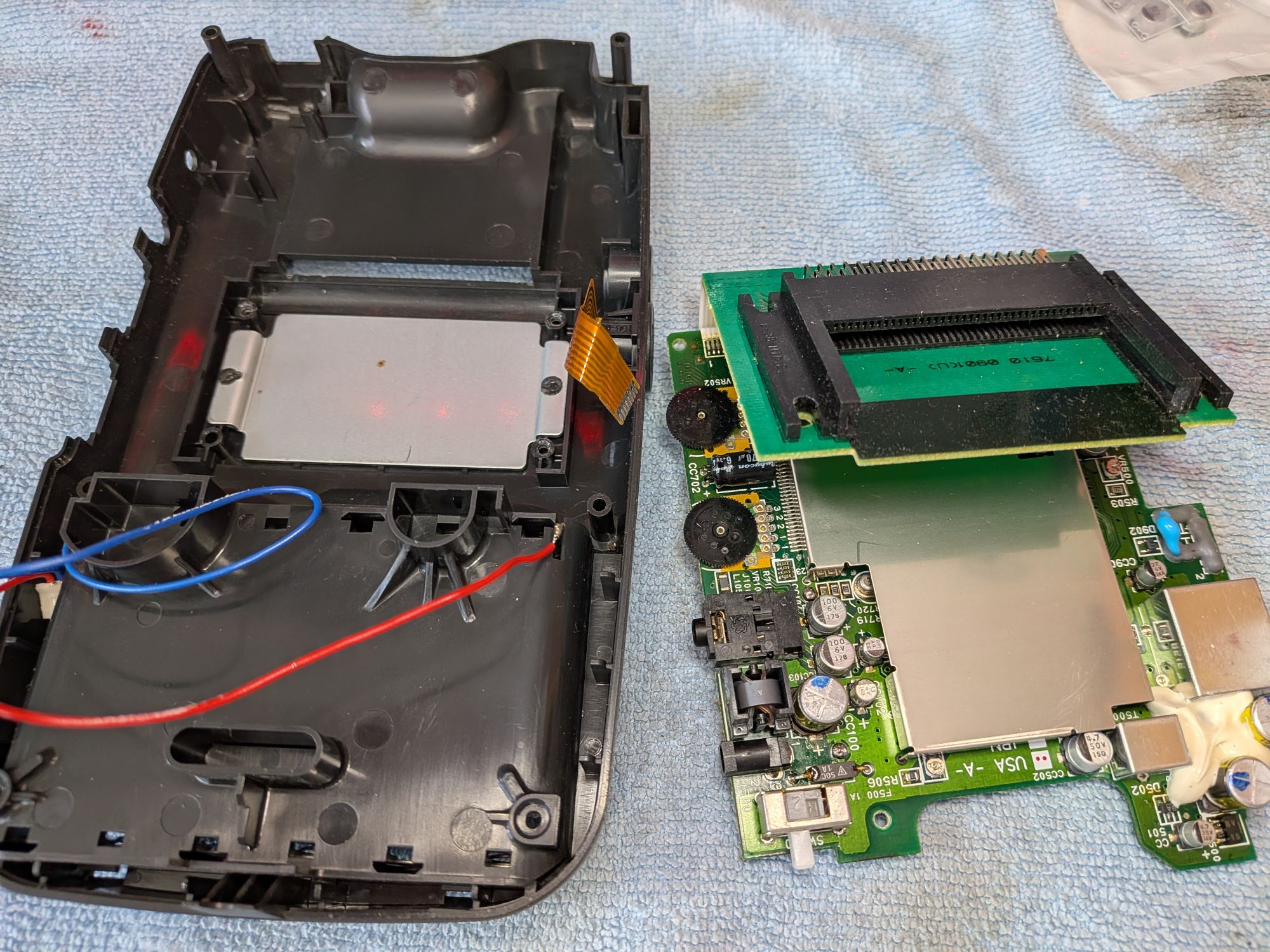
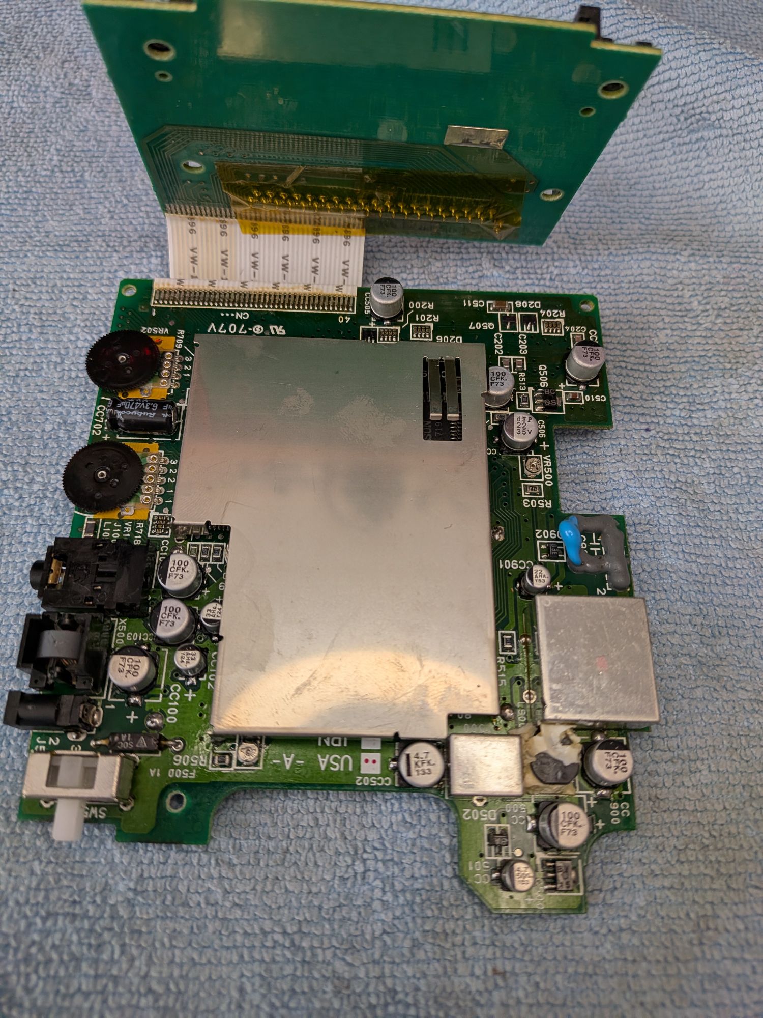
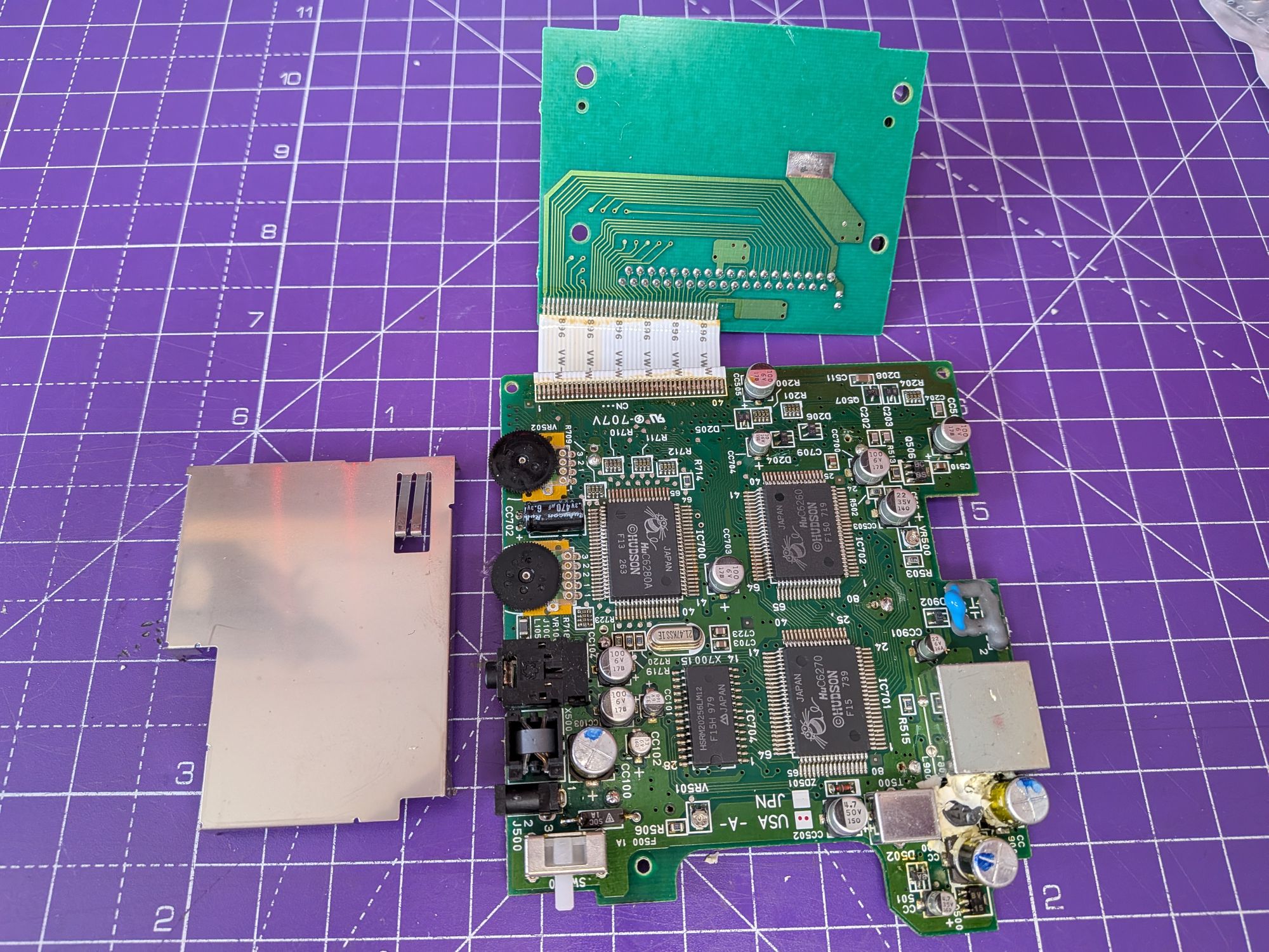
With the board lifted you can now see the soldered ribbon that connects it to the cartridge slot, which incidentally only has 3 screws holding the board in place.
It’s quite similar to the original PC Engine in that regard. It needs to be handled carefully as it will be susceptible to breakage. Not just of the soldered connections but the actual conductor cores too. It’s best not to unfold things like this too much.
The RF shielding is a bit tricky to remove as it has legs which go through the board. Some of the legs are hidden underneath another RF shield on the other side of the board, so it’s best removed by desoldering the inaccessible legs from the top, transferring the heat through the leg into the solder.
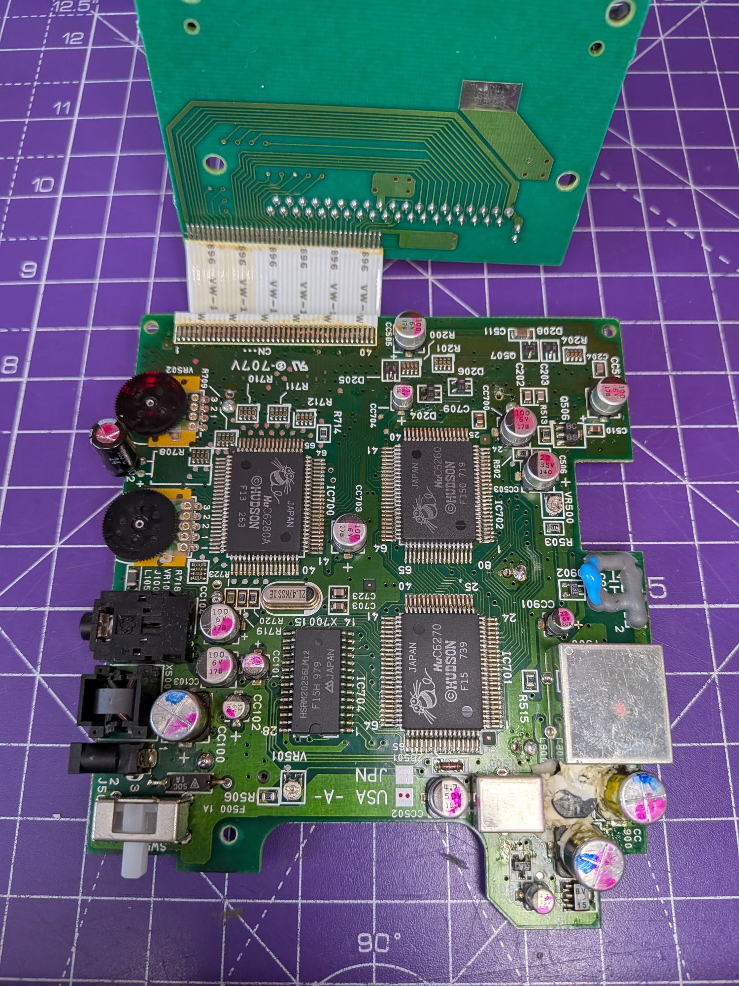
You can now see the board and all the surface mount capacitors there are to change. Some of them are slightly under the RF shield, so it does need to come off. It’s common not to refit it, but we will be doing.
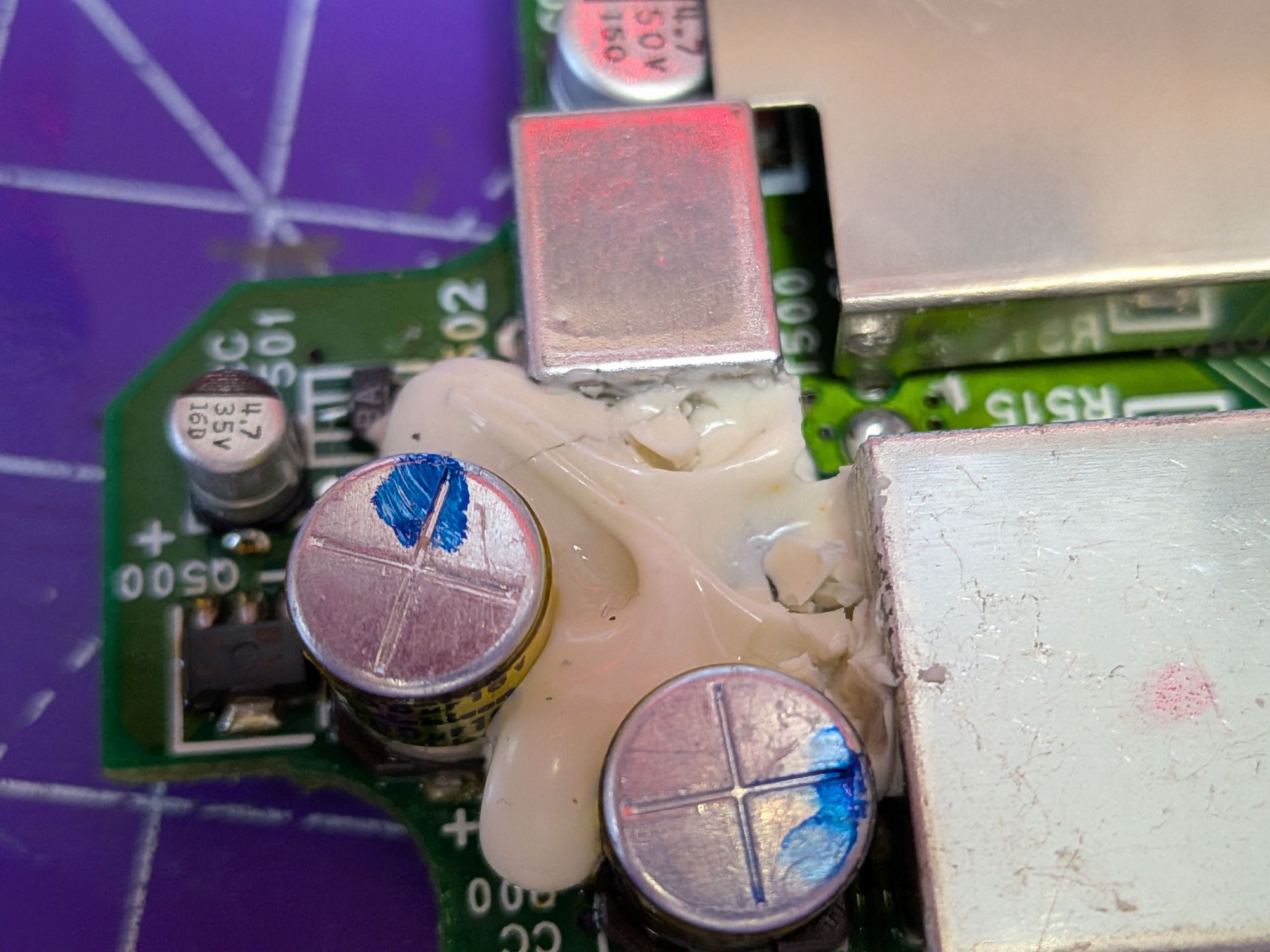
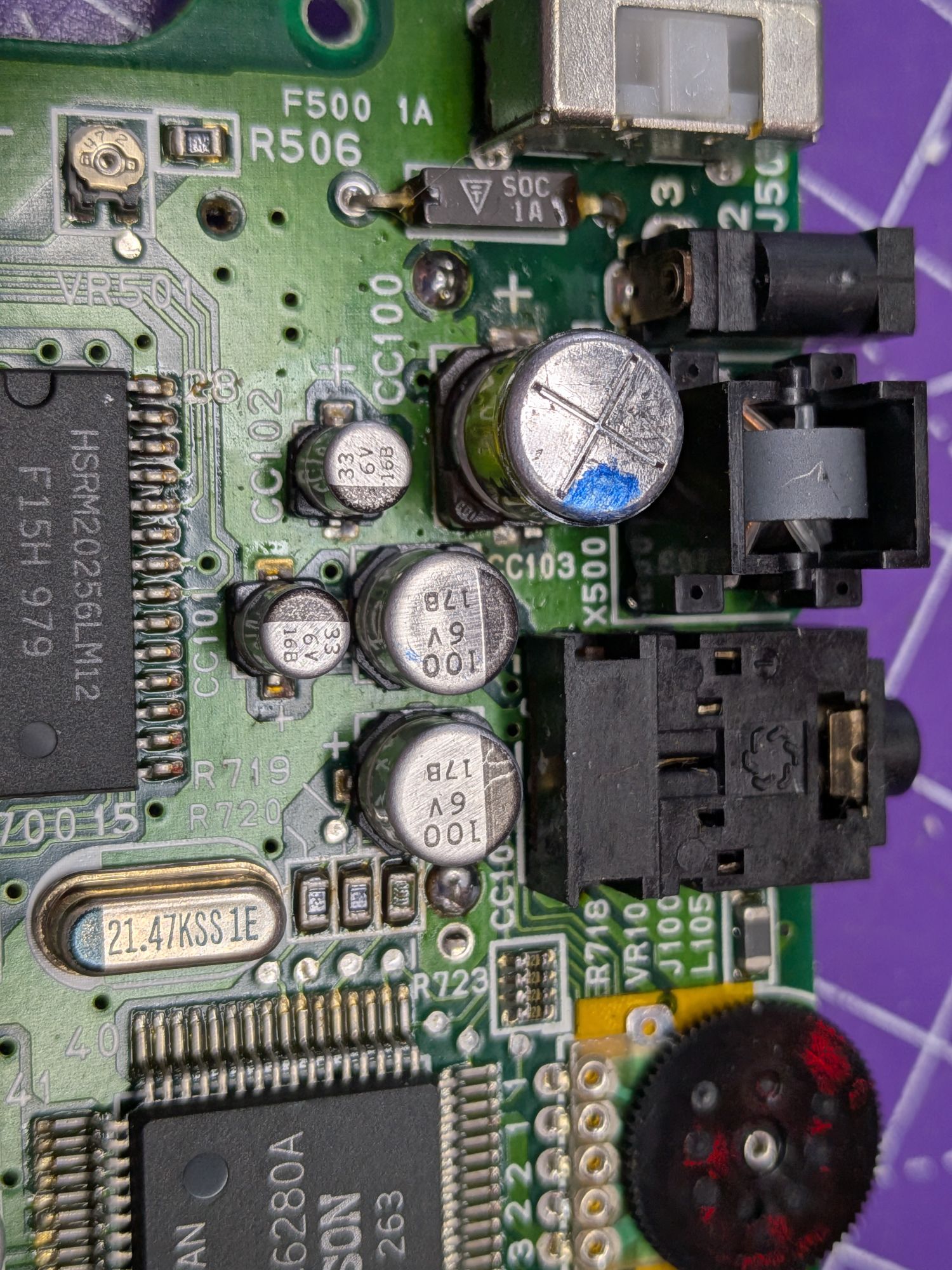
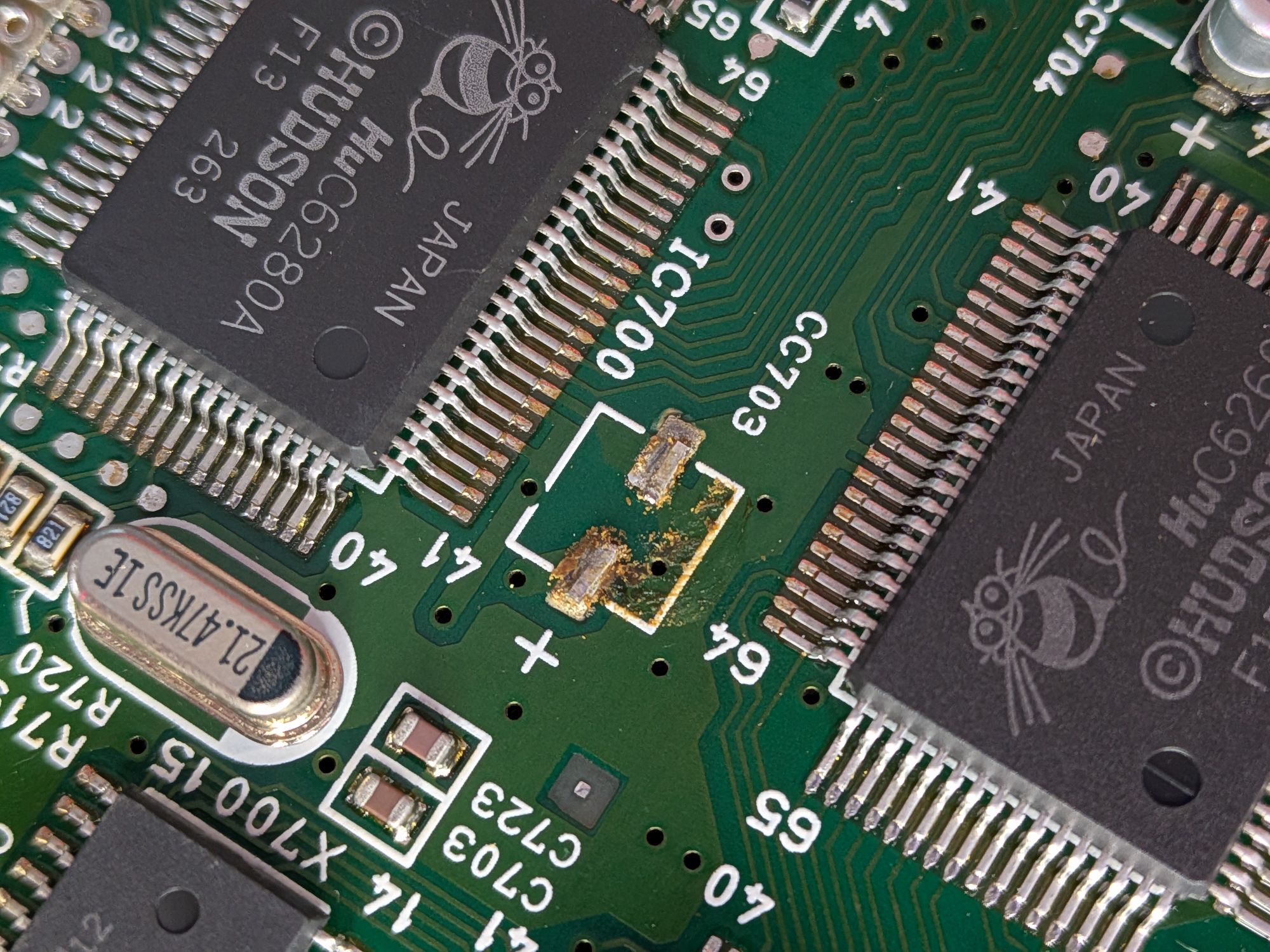
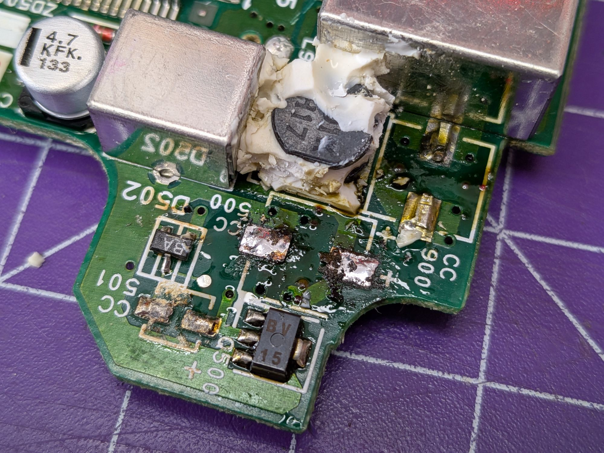
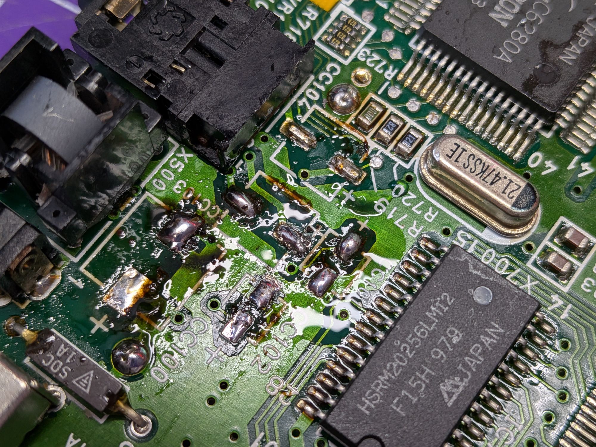
There are some leaky capacitors here. Some have corroded but it seems to be quite localised. Others have leaked but not yet corroded badly.
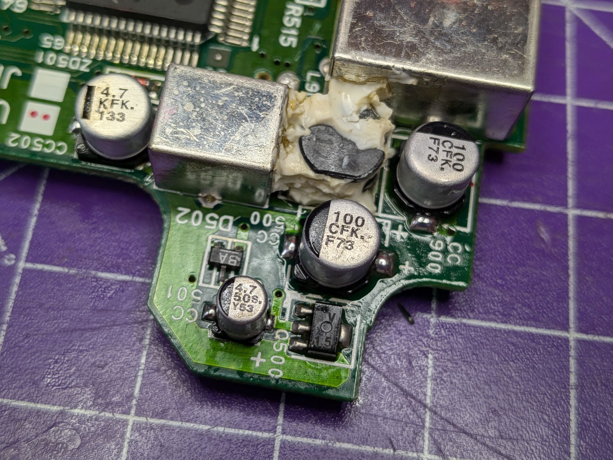
Problem areas are, for one the top corner which has silicon circuit glue blobbed all over it. It’s there to add some mechanical stability to the taller capacitors and perhaps also the coil, as they vibrate very microscopically when being oscillated. The silicon has to be picked off but a bit of IPA helps to loosen it. With the caps removed it looks a bit of a mess but some of that is burned flux. The new capacitors are quite a bit smaller than the 90’s ones.
The other main problem area is the other edge of the board. There are a bunch of capacitors mounted really close to each other, the plastic sockets and some surface mount resistors. They have all leaked but corrosion is minimal here. It all gets a good cleaning before the new ones go on.
With the main board done and the RF shield refitted there is one other problem capacitor lurking, easily missed but just as important. It is a through hole miniature cap on the button board and prone to leaks. It can devastate the carbon traces of the button board.
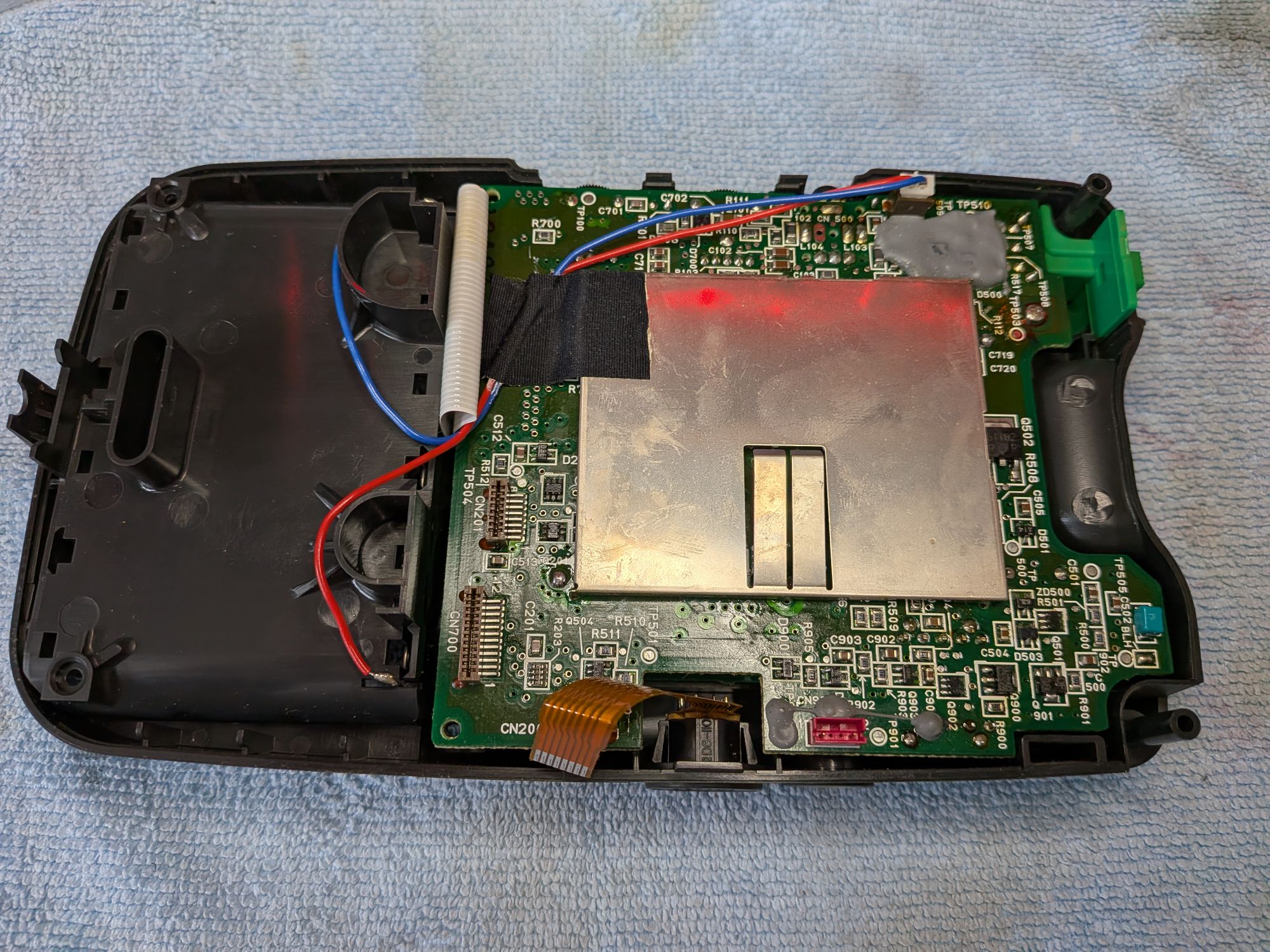
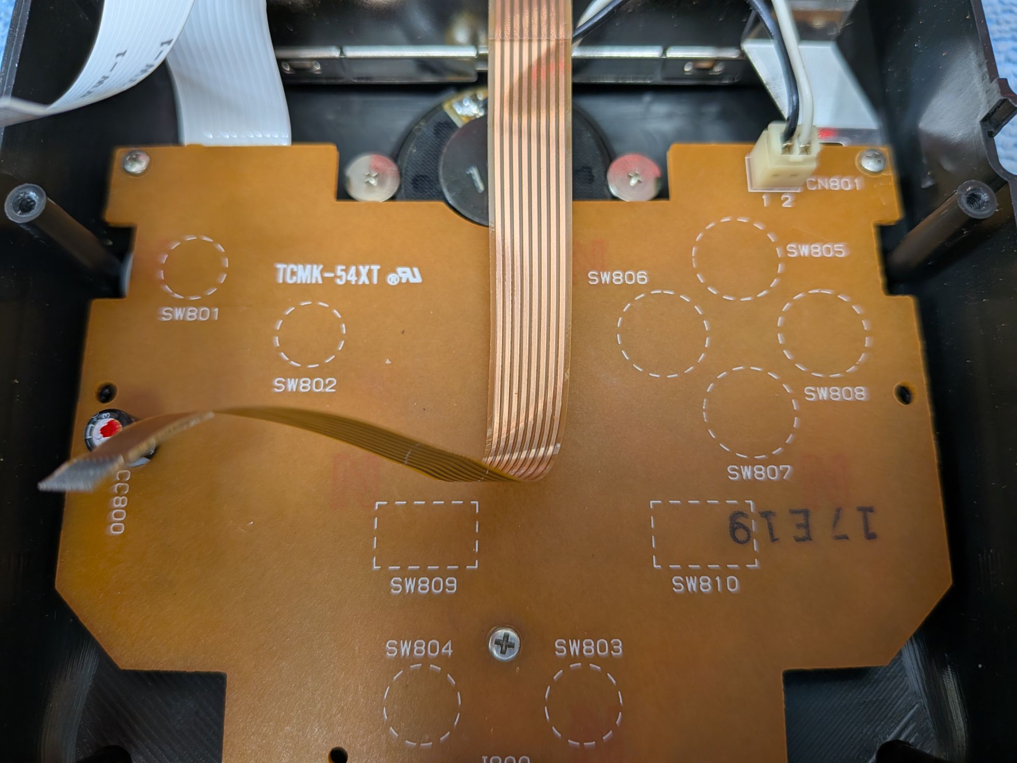
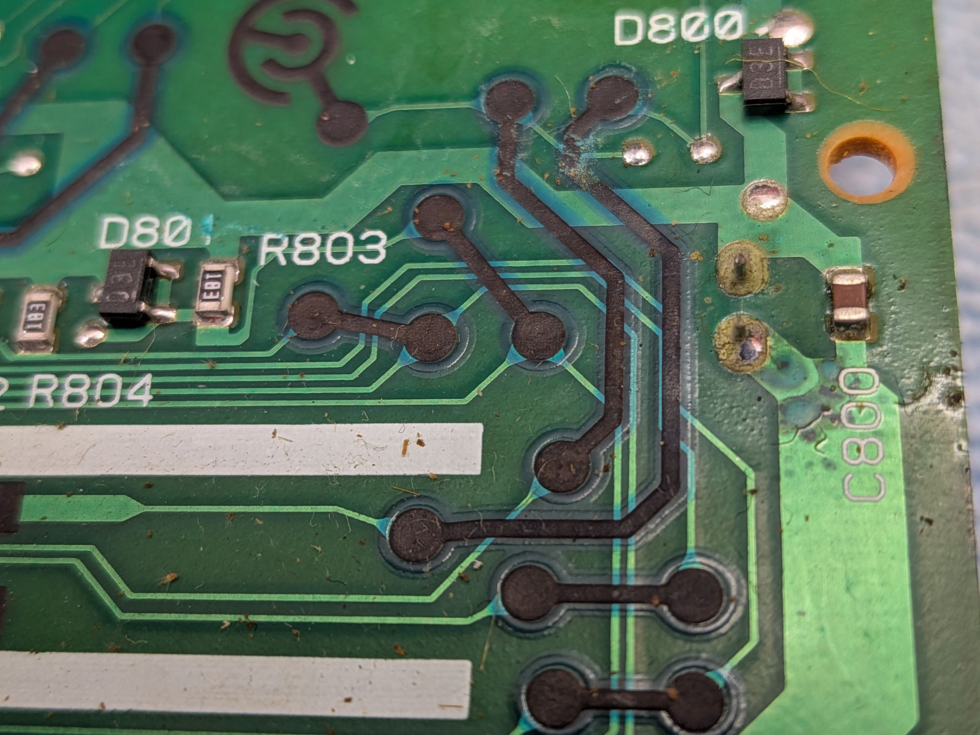
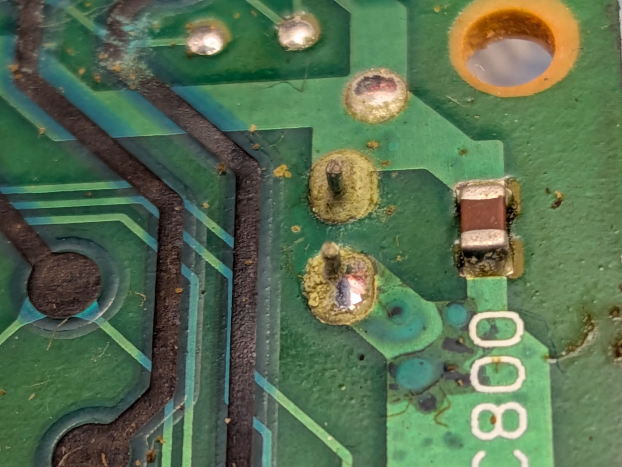
The pics show the offending capacitor and the carbon traces. This was a 90’s thing. A cheap way to avoid having to use a two layer, double sided, board. You often see it on Boombox boards, which often use printed carbon resistors too. Just a cost saving measure. Here they are used over the top of the normal copper traces, the green ones, to jump from one point to another point. Very vulnerable to corrosion but repairable if it does happen.
You can see how the leaked electrolyte from that tiny cap has found its way through the solder and begun to corrode the copper traces here. That can’t be ignored. It has to be exposed and treated, to prevent the rot from travelling along the length of it. I usually grind it back to the copper and flow solder over the top of it to protect it. Luckily the carbon traces are not badly affected.
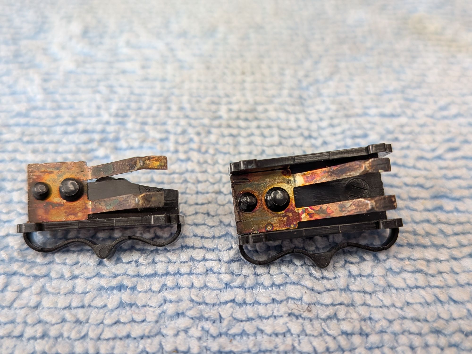
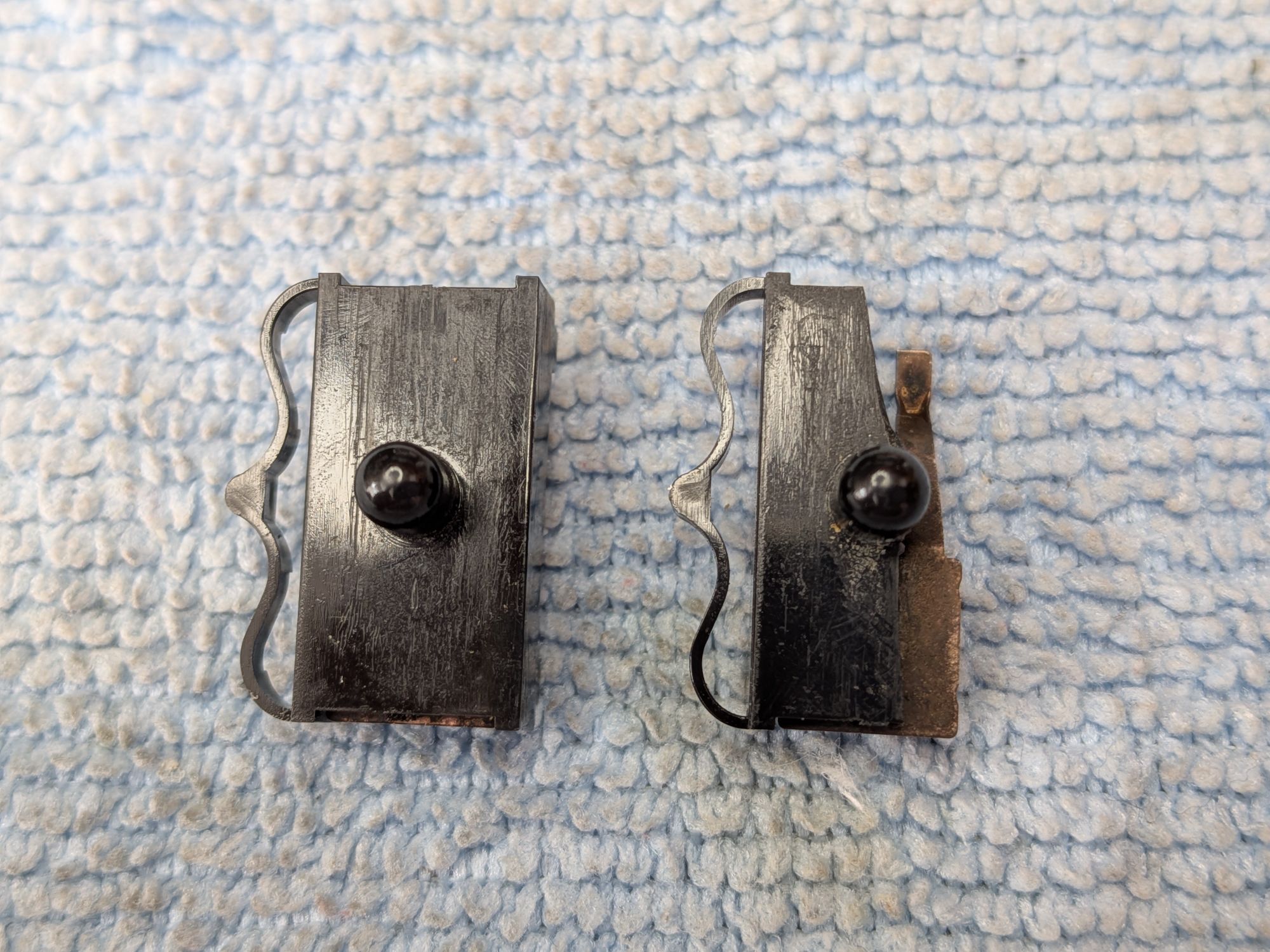
Giving the buttons and contacts a clean whilst in here found the two slide switches for the auto fire corroded too despite being half way across the board. The gas given off by the electrolyte will have caused this. It polished off OK though.
While they were out I noticed one of the switches has some missing plastic. It was not inside the case either, long gone, which makes it not sit properly inside the channel it is supposed to run along. This could perhaps be built back up with some melted plastic, and carved into shape but I think would show through the front of the case. Maybe a 3D printed replacement would be better. For now though I replaced it as the auto fire switch for button 2, which is likely least used.
So with everything now finished it is FINALLY time for some “Play Testing” ™! What a wonderful thing it is. Incidentally, post-recap it now draws 570mA, which is less.
2 Responses
What an awesome repair and a great blog post.
Thanks Garron. It is a wonderful thing isn’t it. Need a bank loan for the batteries though!