

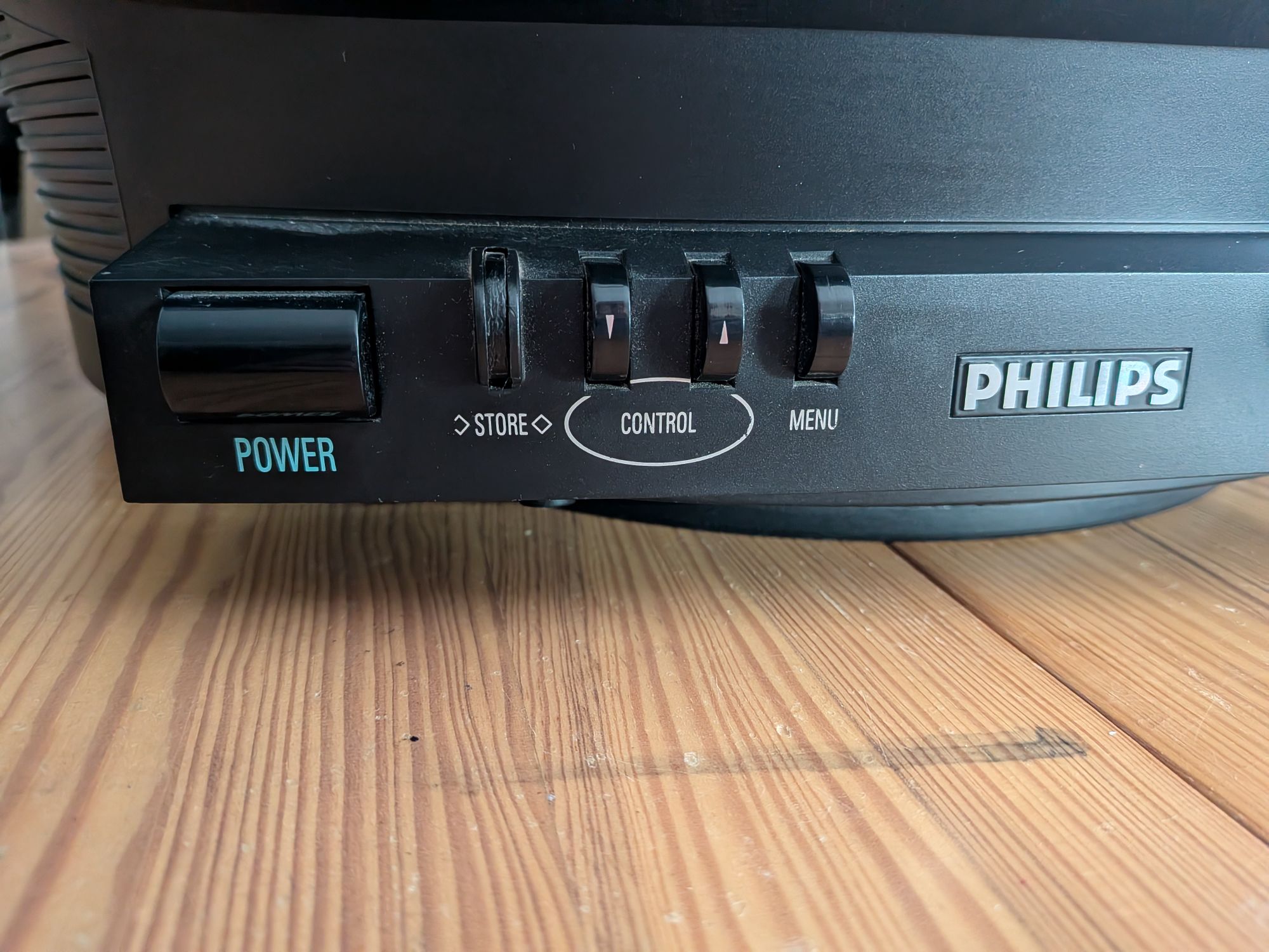
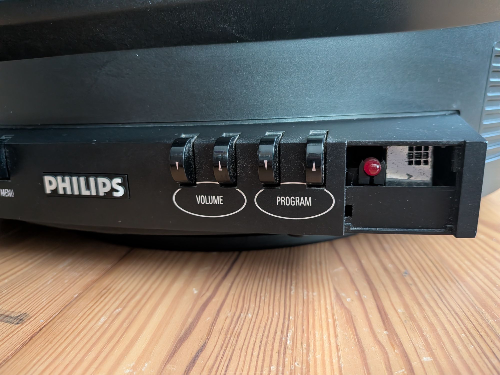
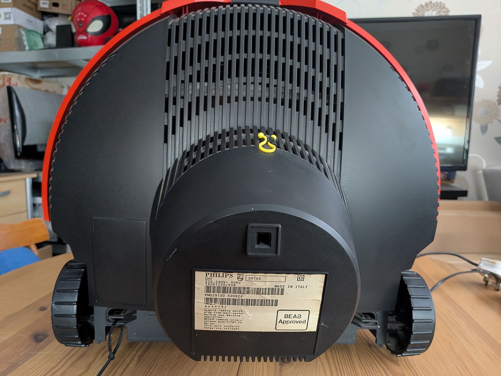
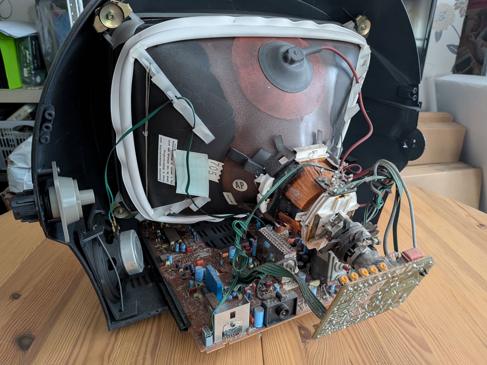
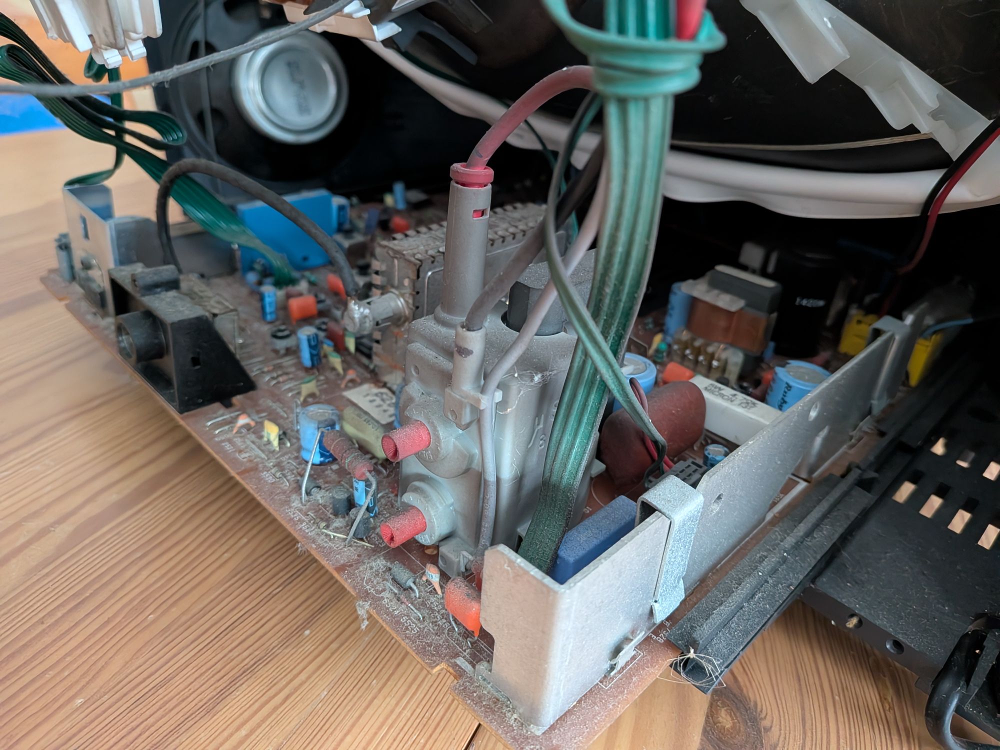
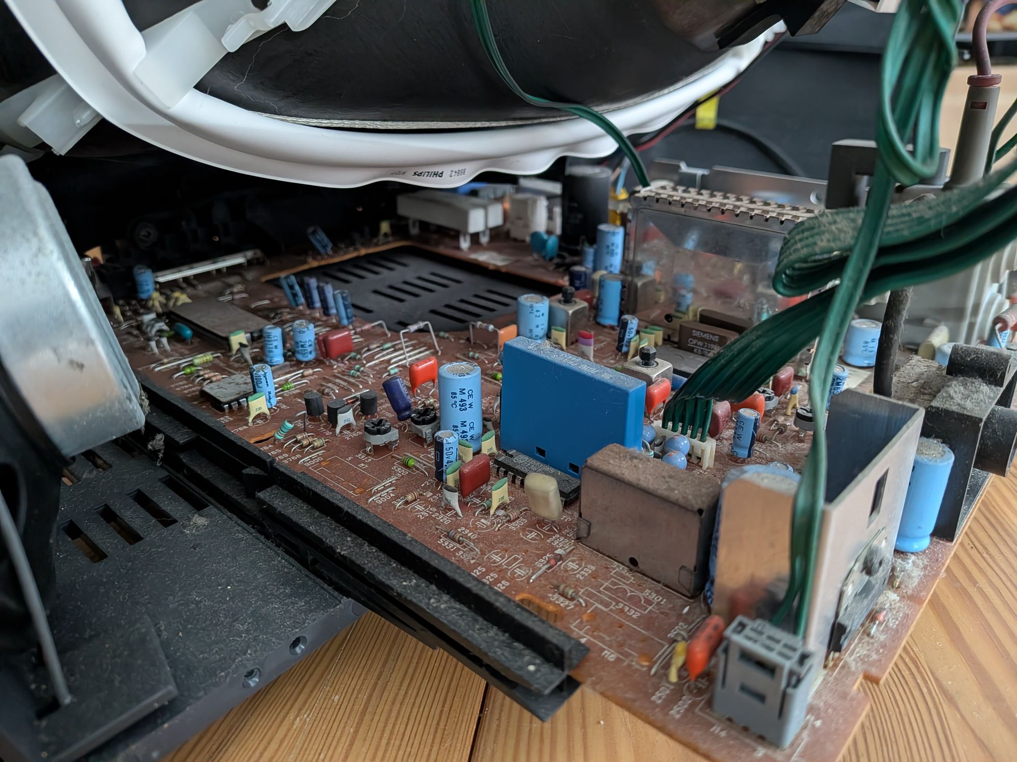
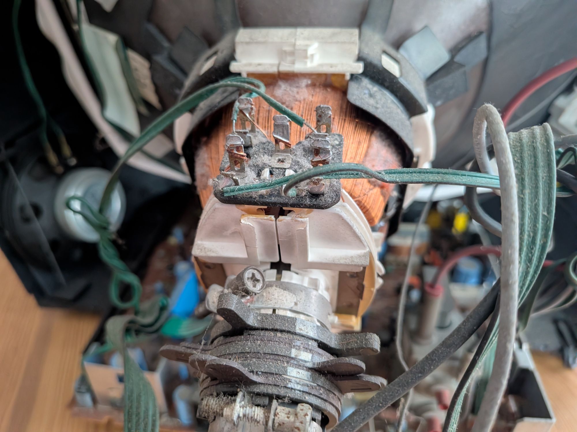
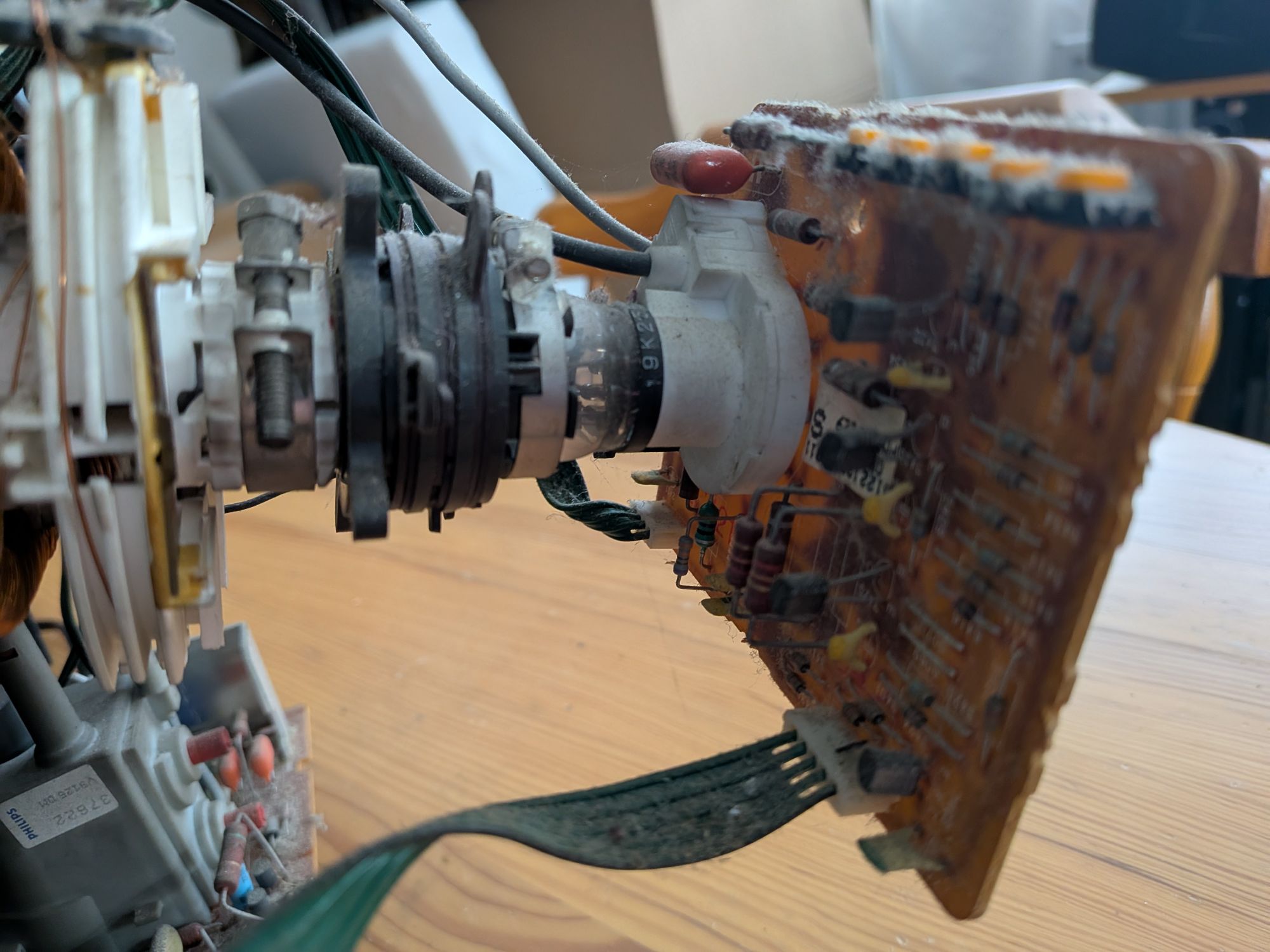
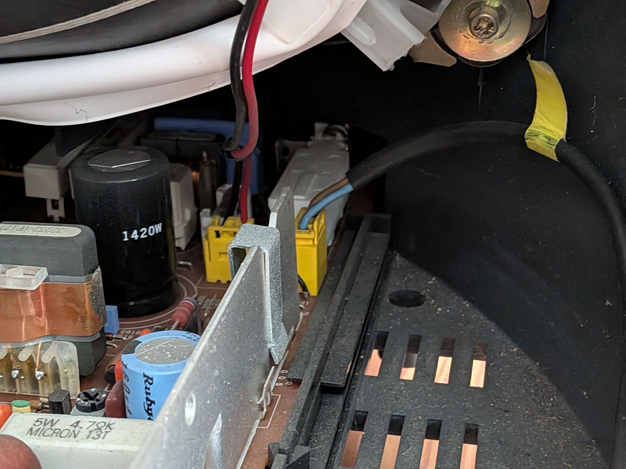
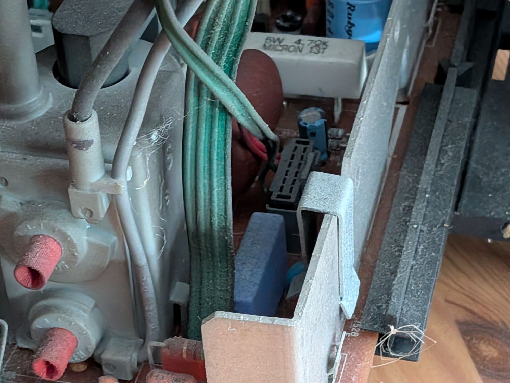
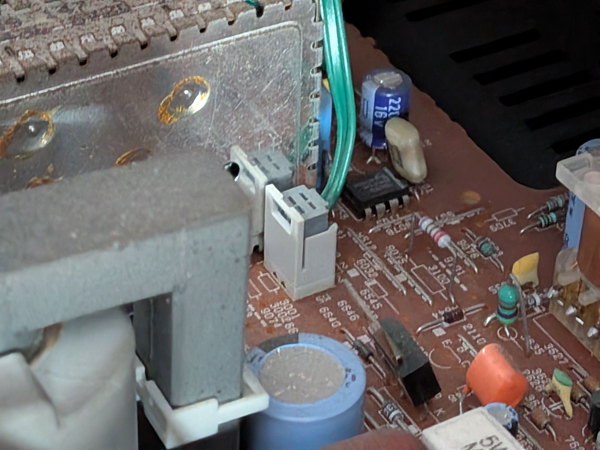
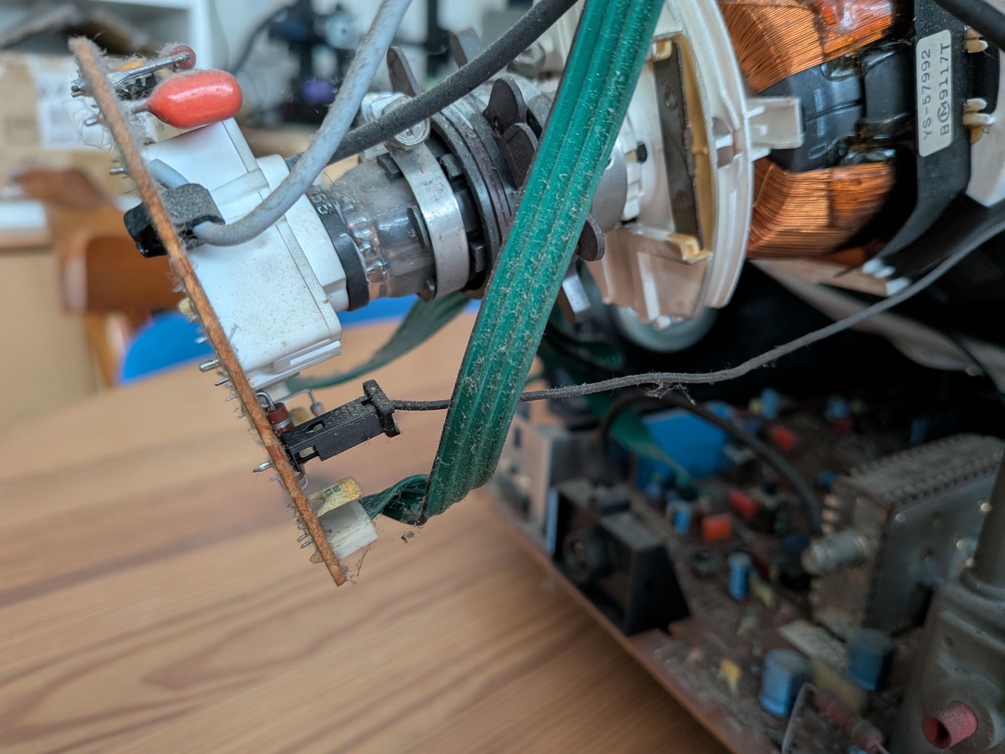
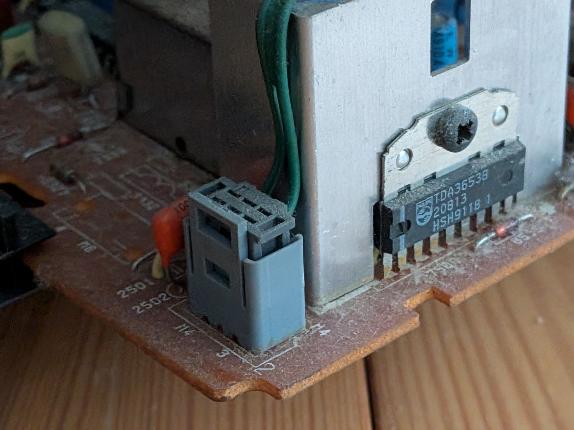
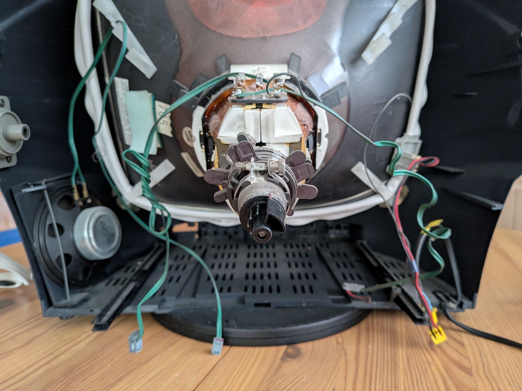
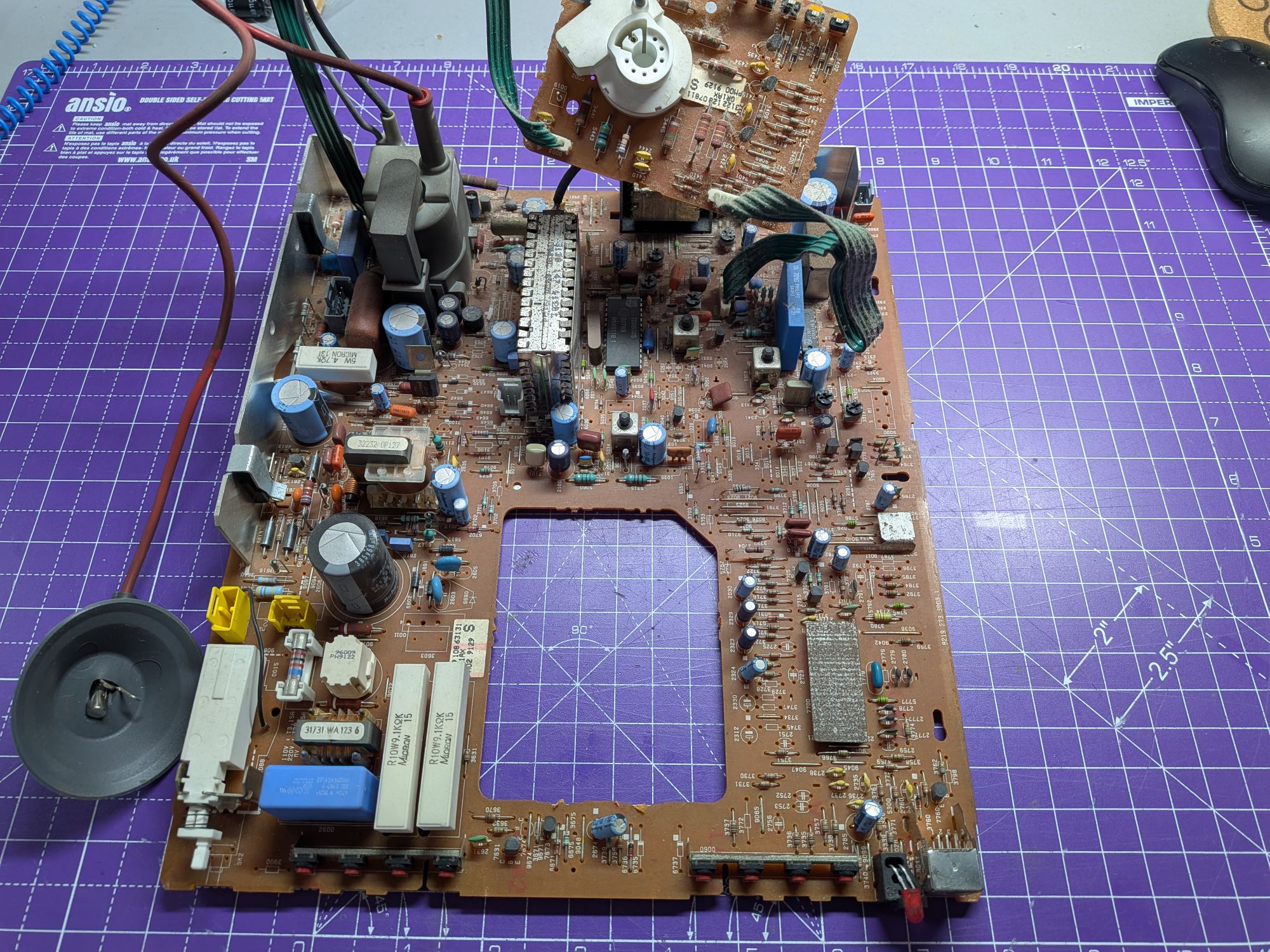
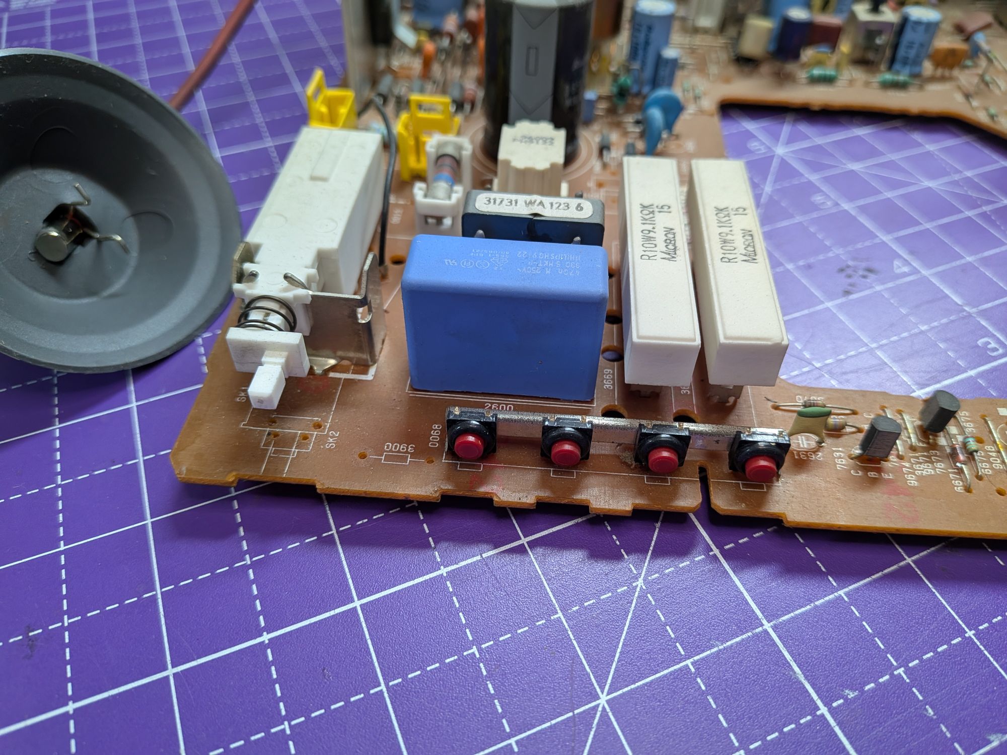
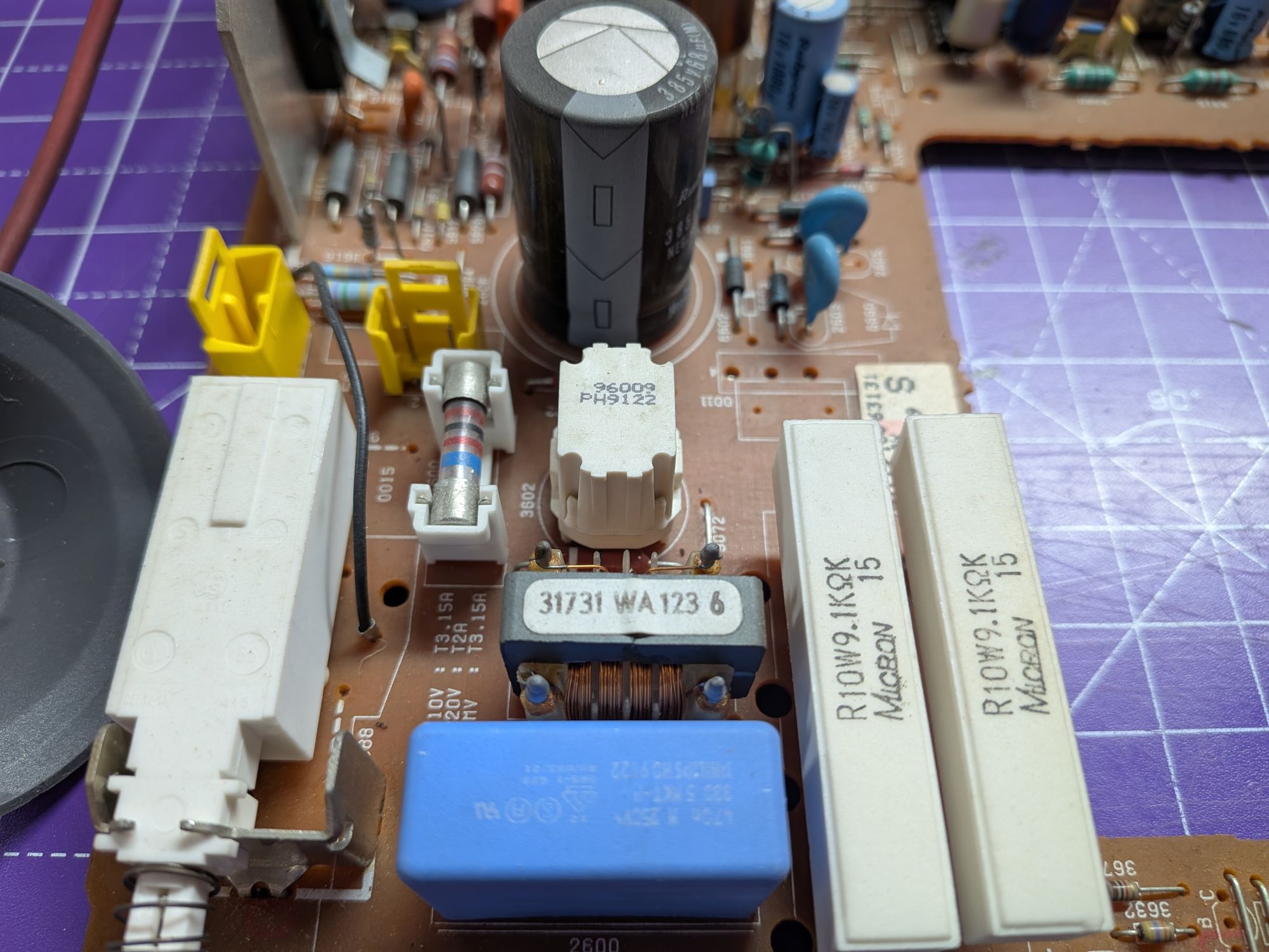
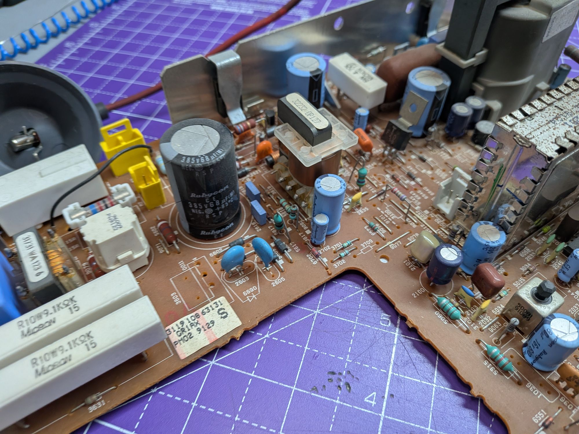
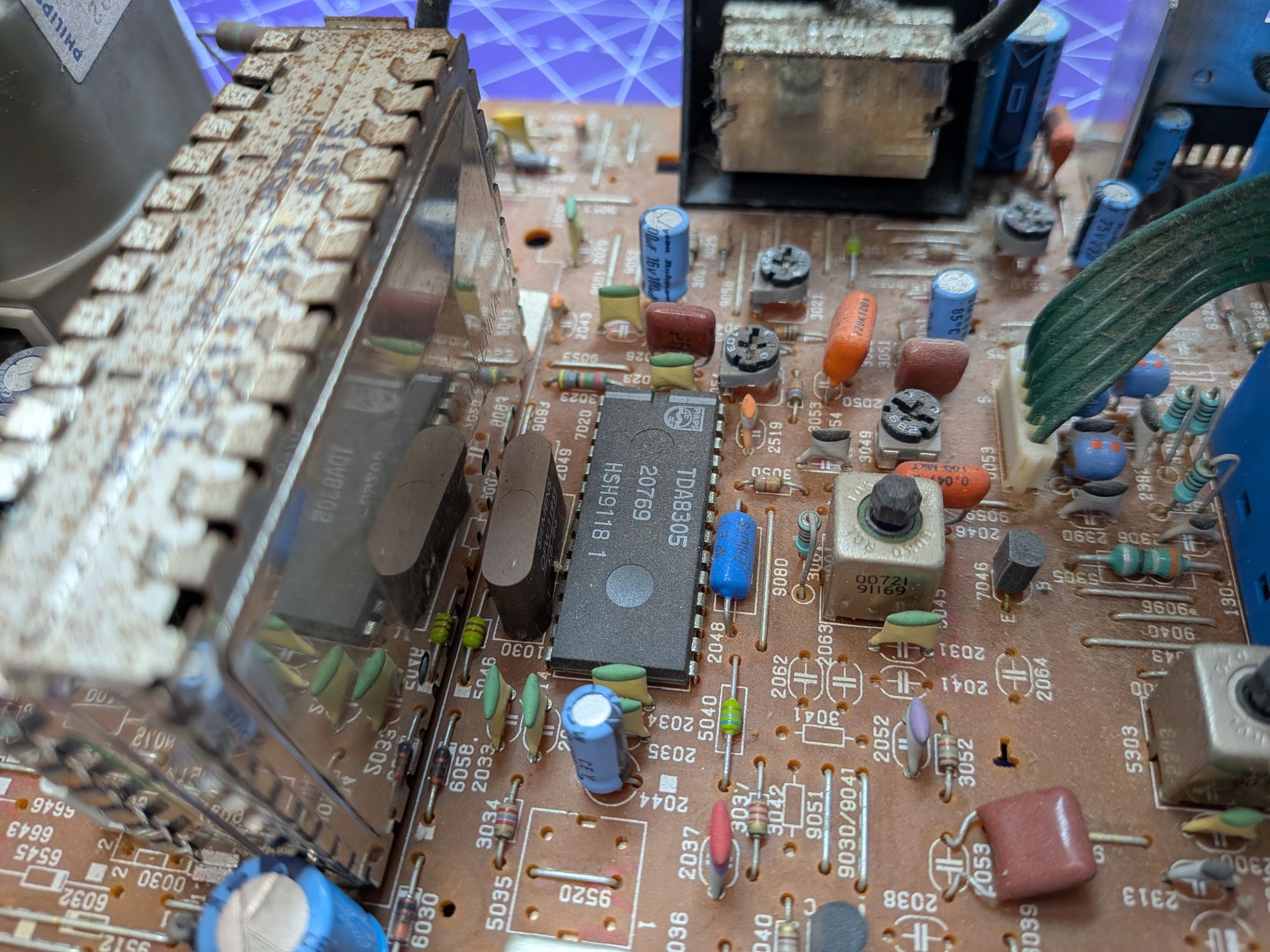
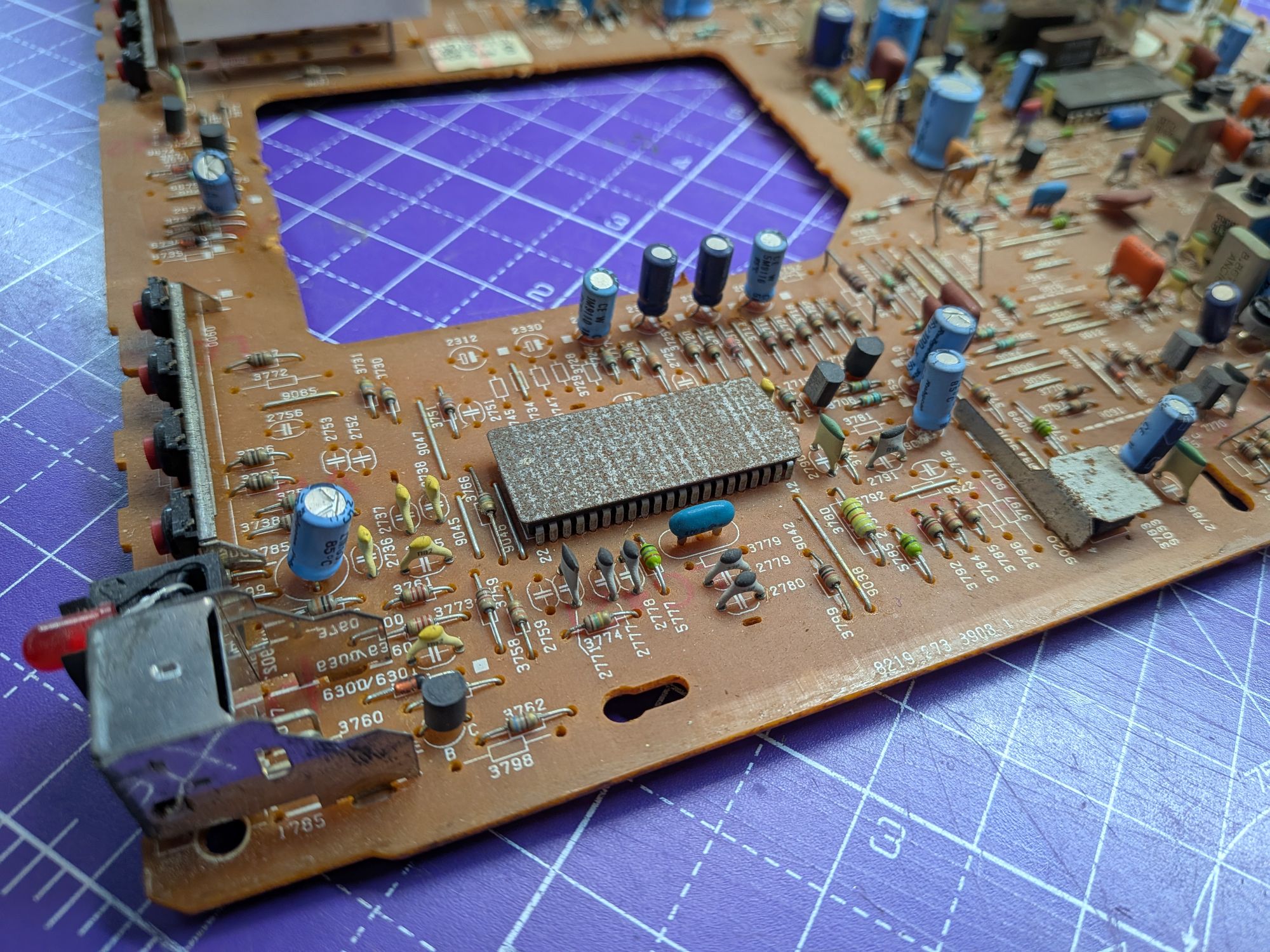
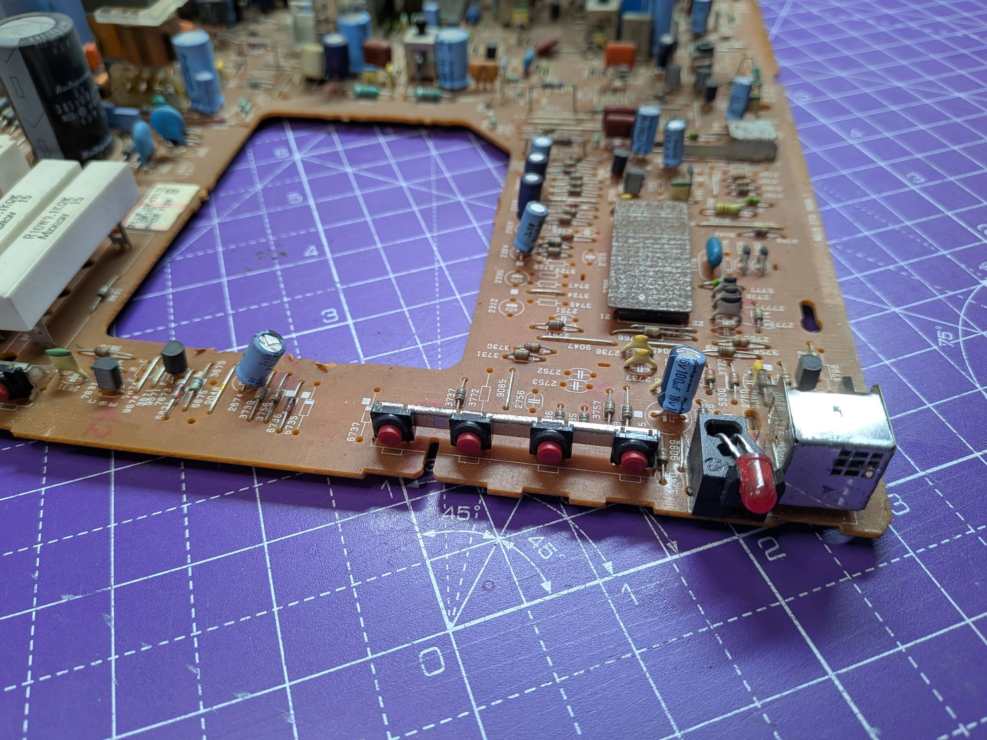
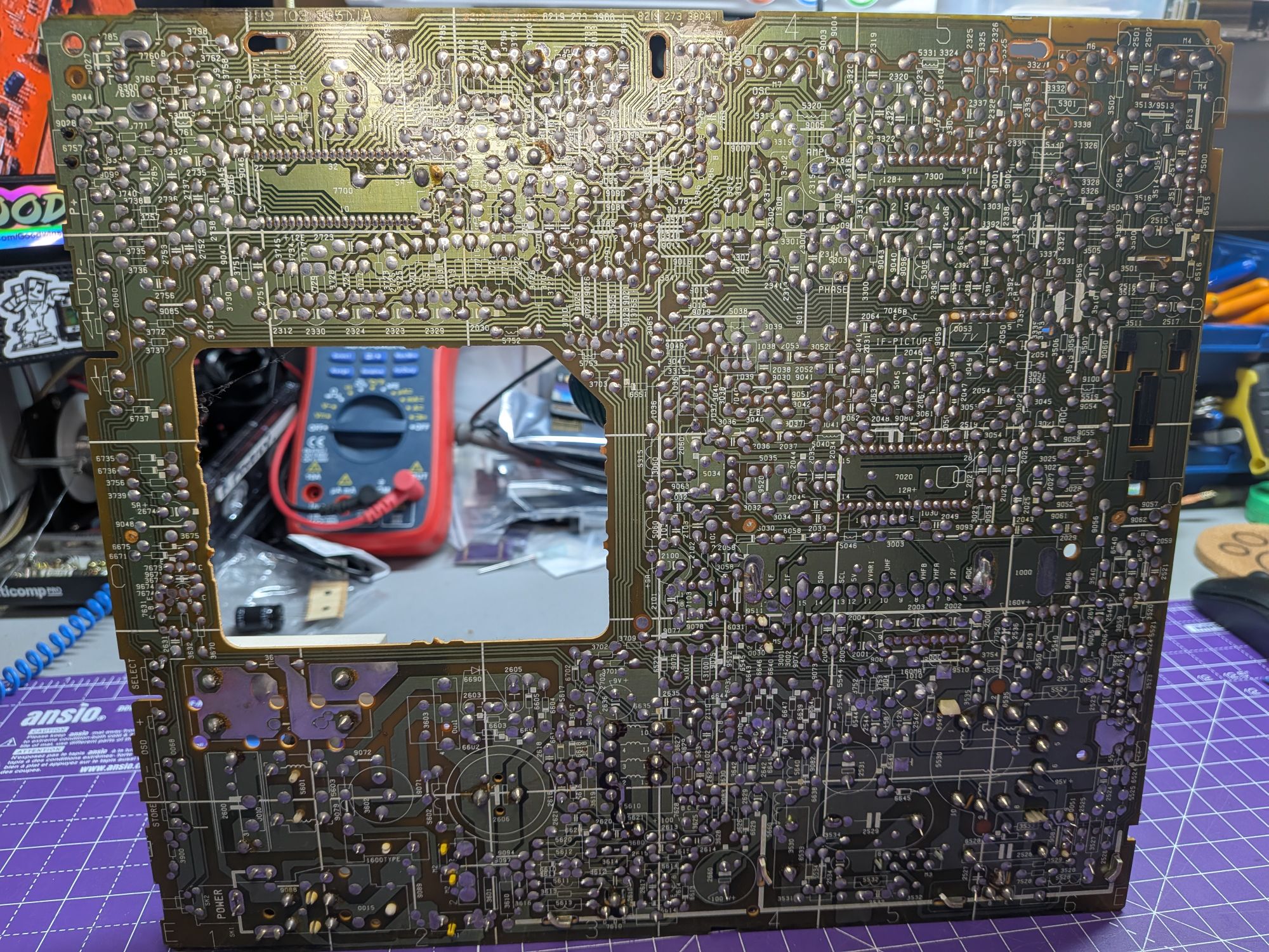
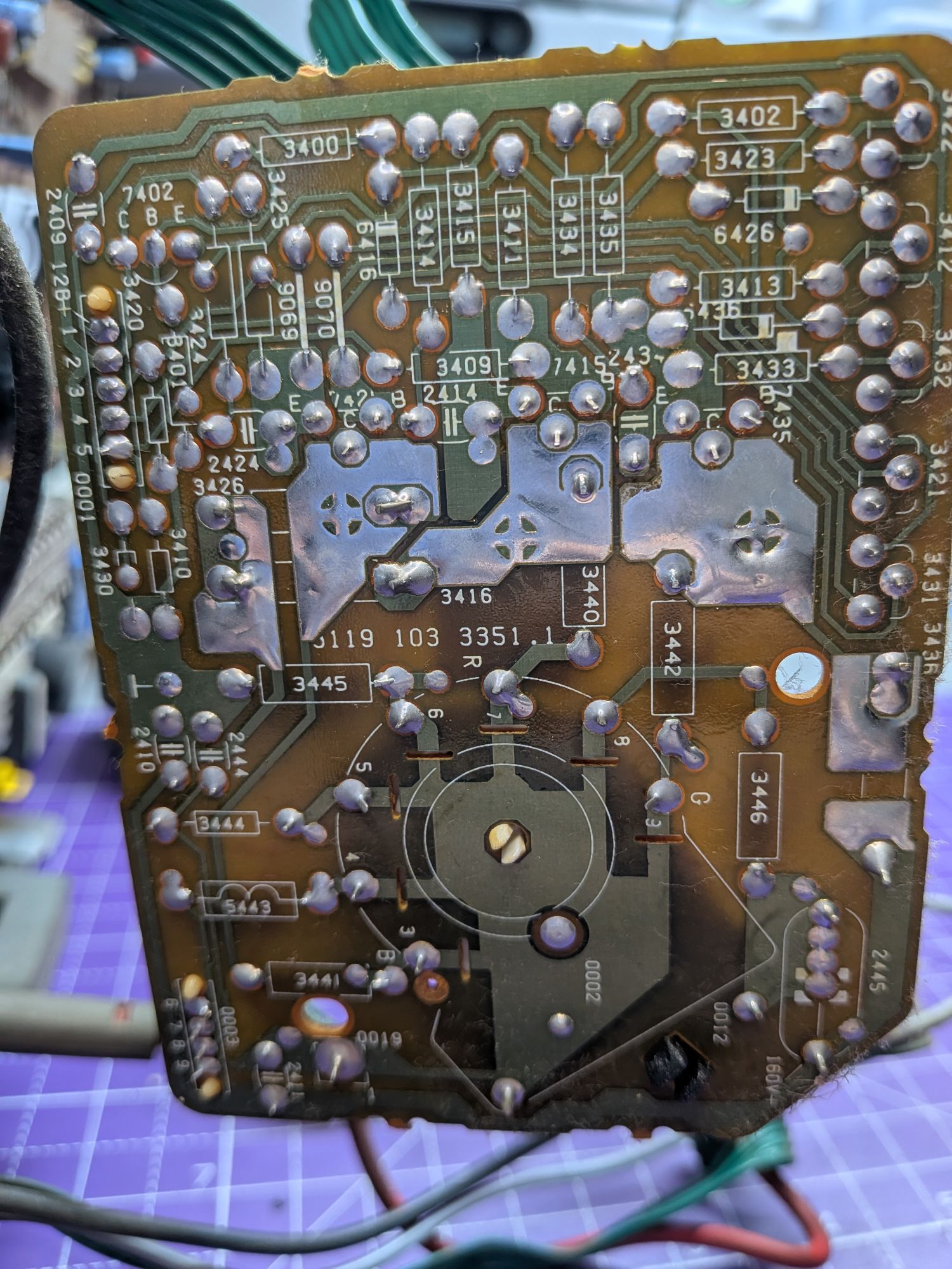
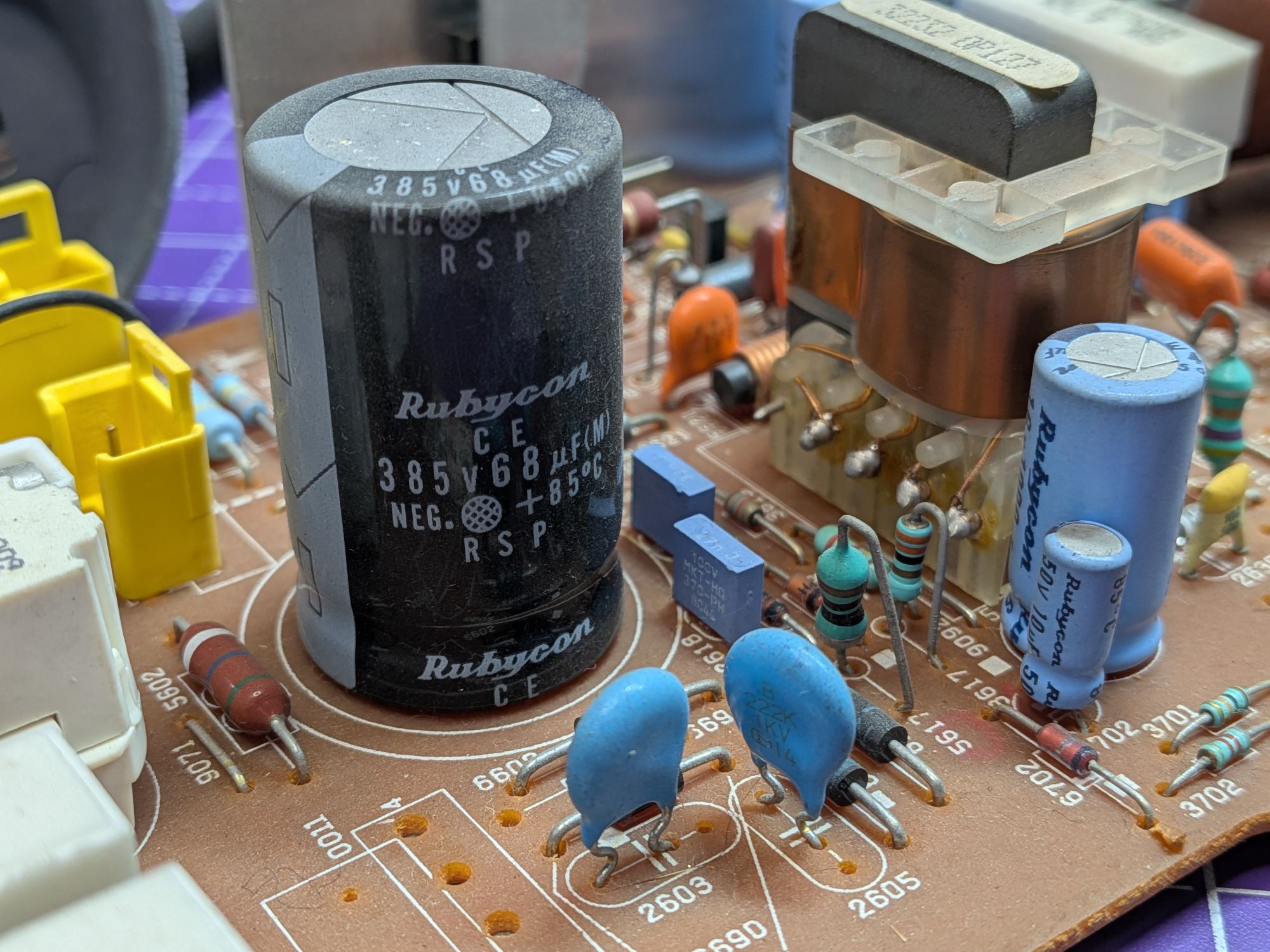
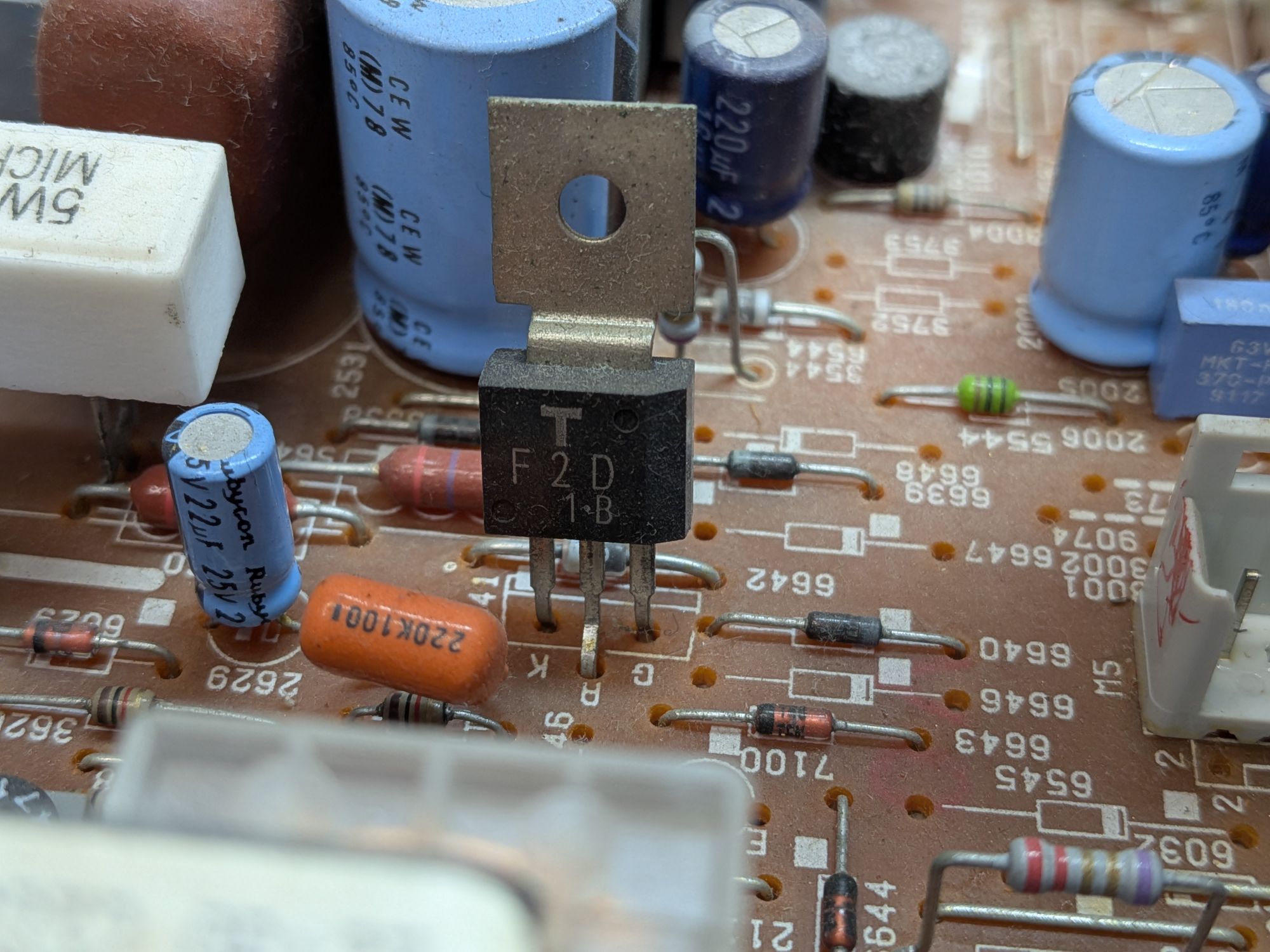
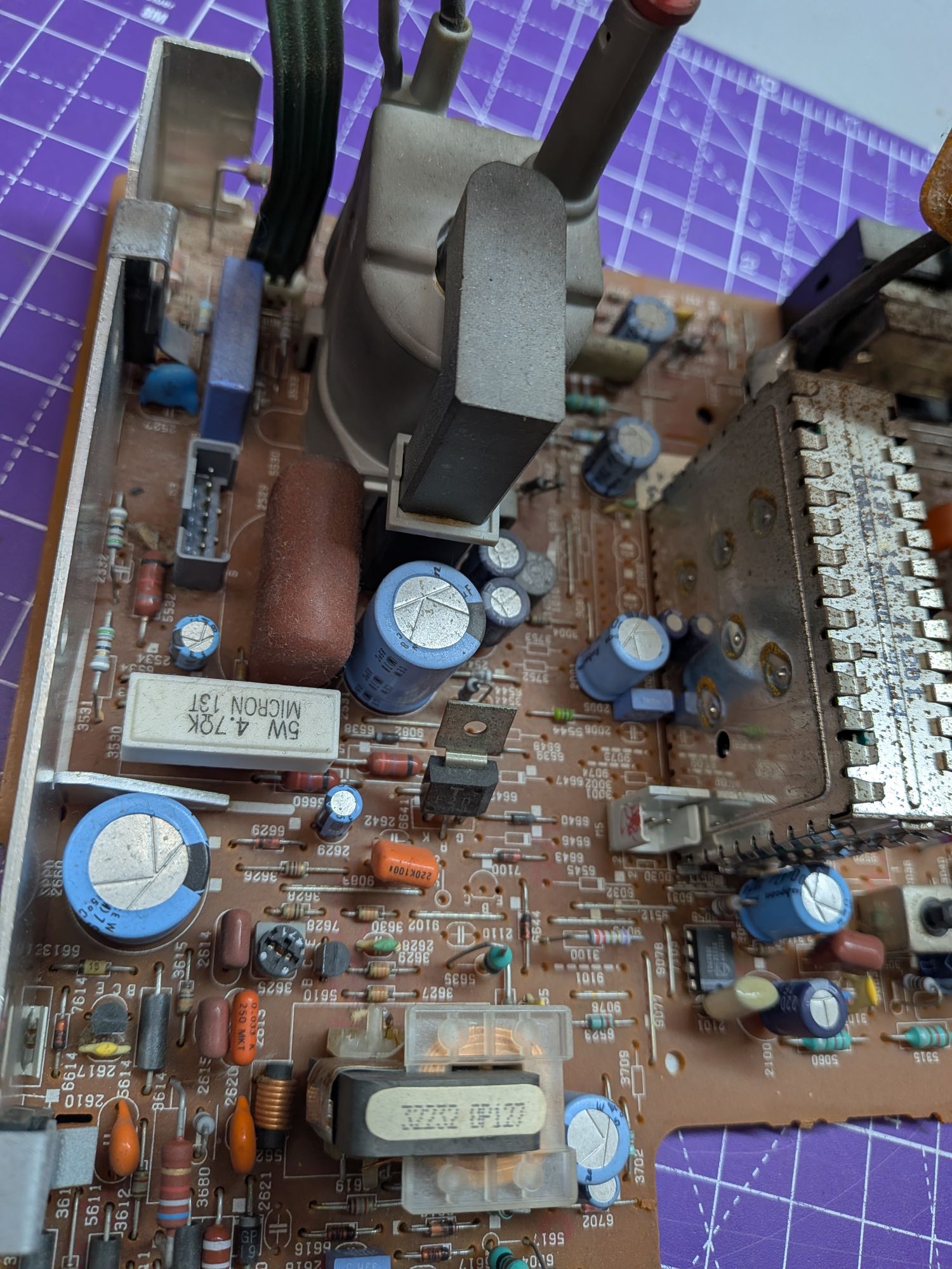
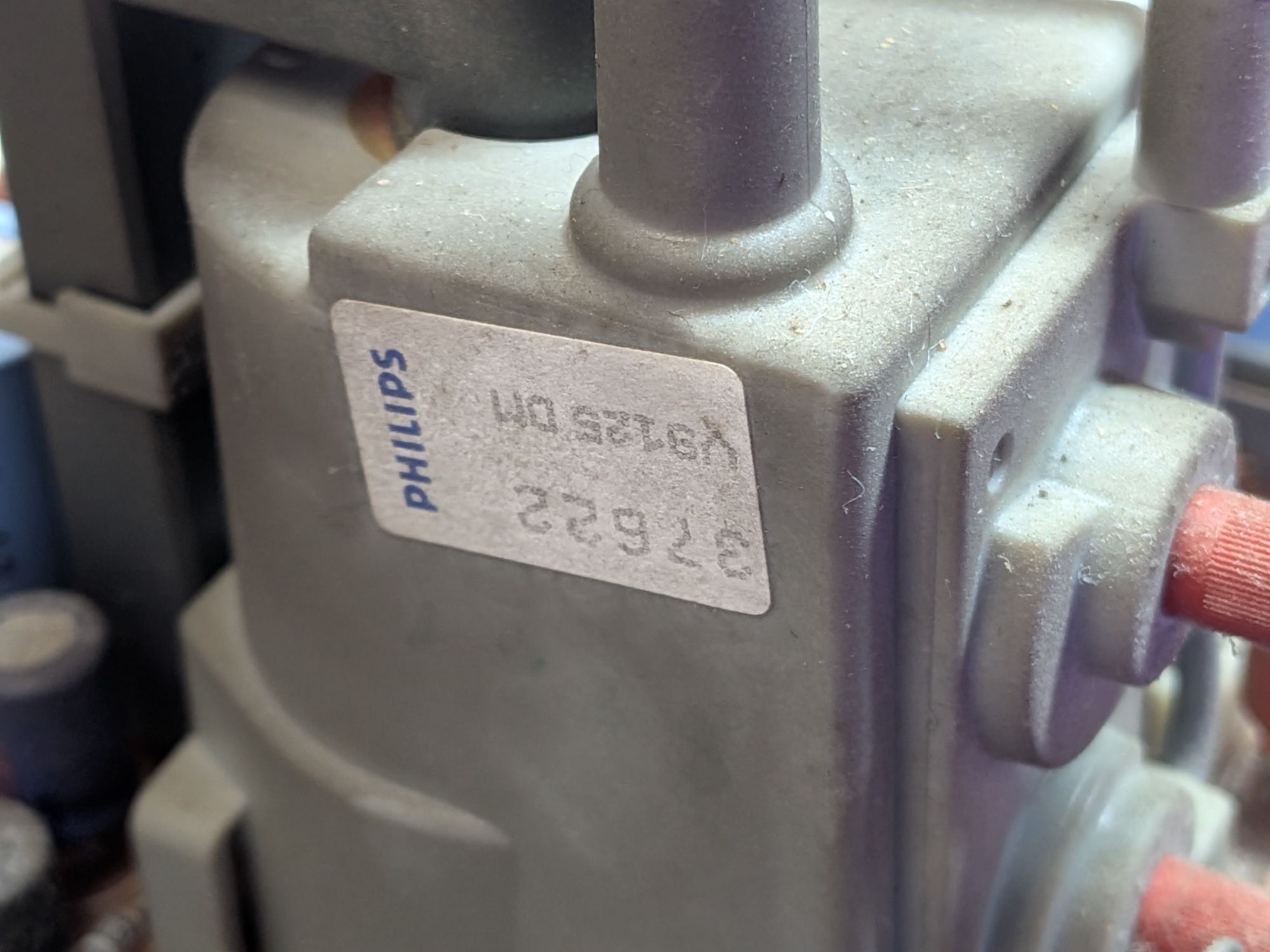
The pics show the bottom of the boards. They were both inspected visually for any dry solder joints, which are a common problem in CRTs, but everything appears to be in remarkably good shape, all things considered.
The nature of the fault, the way it died and the behaviour of the power LED, suggest there may be a short somewhere. It seems to be trying to power up but is not able to and shutting down. It may even detect the fault as an over-current and protect itself, in that way.
The first thing to check though is the power supply. Always start at the beginning.
It’s not possible to power the board on the bench really, and initial checks don’t include delving into the service manual to find test points and voltages anyway.
For a start it helps to use the tried and trusted K.I.S.S engineering principle. Keep-It-Simple-Stupid.
Applying that here to check the various components individually, in circuit. There’s a kind of hierarchy of general failure points to work through. Silicon components such as transistors and diodes are at the top of the list. When they fail, they tend to fail as a short circuit. Not always, but on the whole.
Quickly going over the various diodes in the power supply and the main power transistors, all appeared good. The next big silicon is in the horizontal circuit.
The horizontal circuit is important as it is what powers and drives the rest of the TV. It is a high power oscillator essentially, which switches power on and off to the primary coil of the flyback transformer, oscillating it. It is driven by some smaller transistors, which in turn power a much larger power transistor called the Horizontal Output Transistor, or HOT.
Given the way that the TV died, it seems likely to have been a short on one of the secondary windings of the flyback. Possibly causing damage to the flyback itself, so this section was important to check over.
As the flyback is oscillated it provides power on the secondary windings, in much the same way as a switching power supply. It is used to power much of the board and provide the correct deflection timings. There are several secondary windings, one of which is the high voltage winding for the anode of the tube.
A common point of failure is the HOT. It handles a lot of power and is subjected to potential high voltage spikes if other issues exist. A quick check showed it was completely shorted. All three legs shorted together.
This would have been essentially putting a dead short across the output of the power supply. Not ideal, as it’s also connected to the primary flyback winding. It could easily dissipate all that energy through the flyback and kill that too.
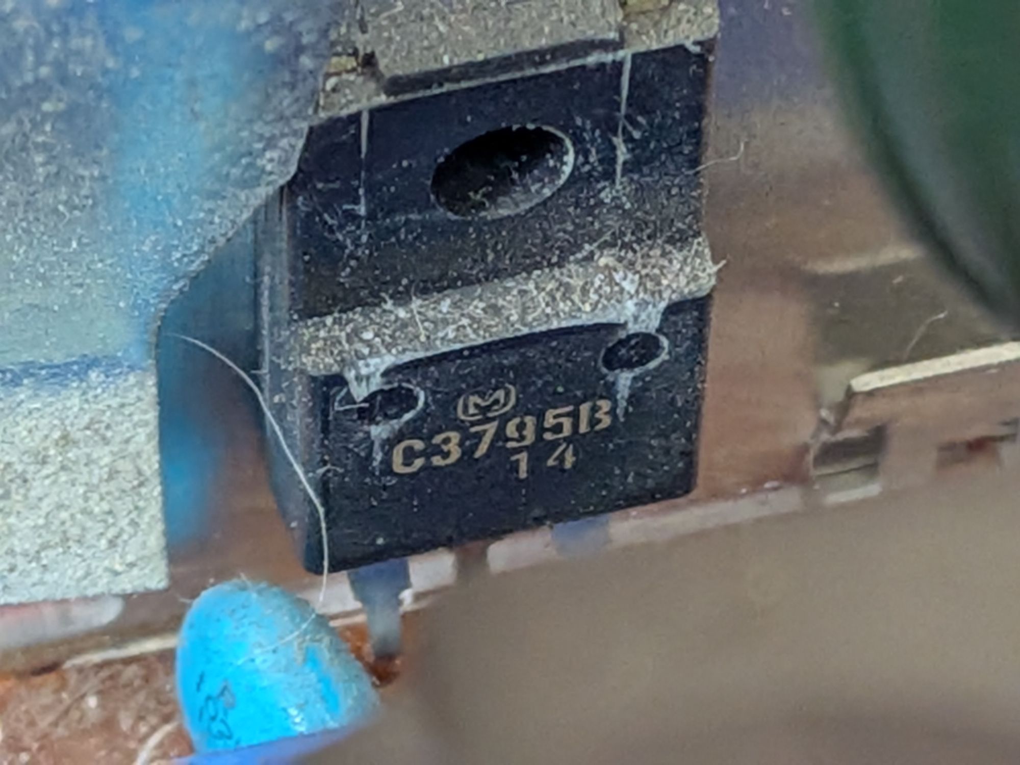
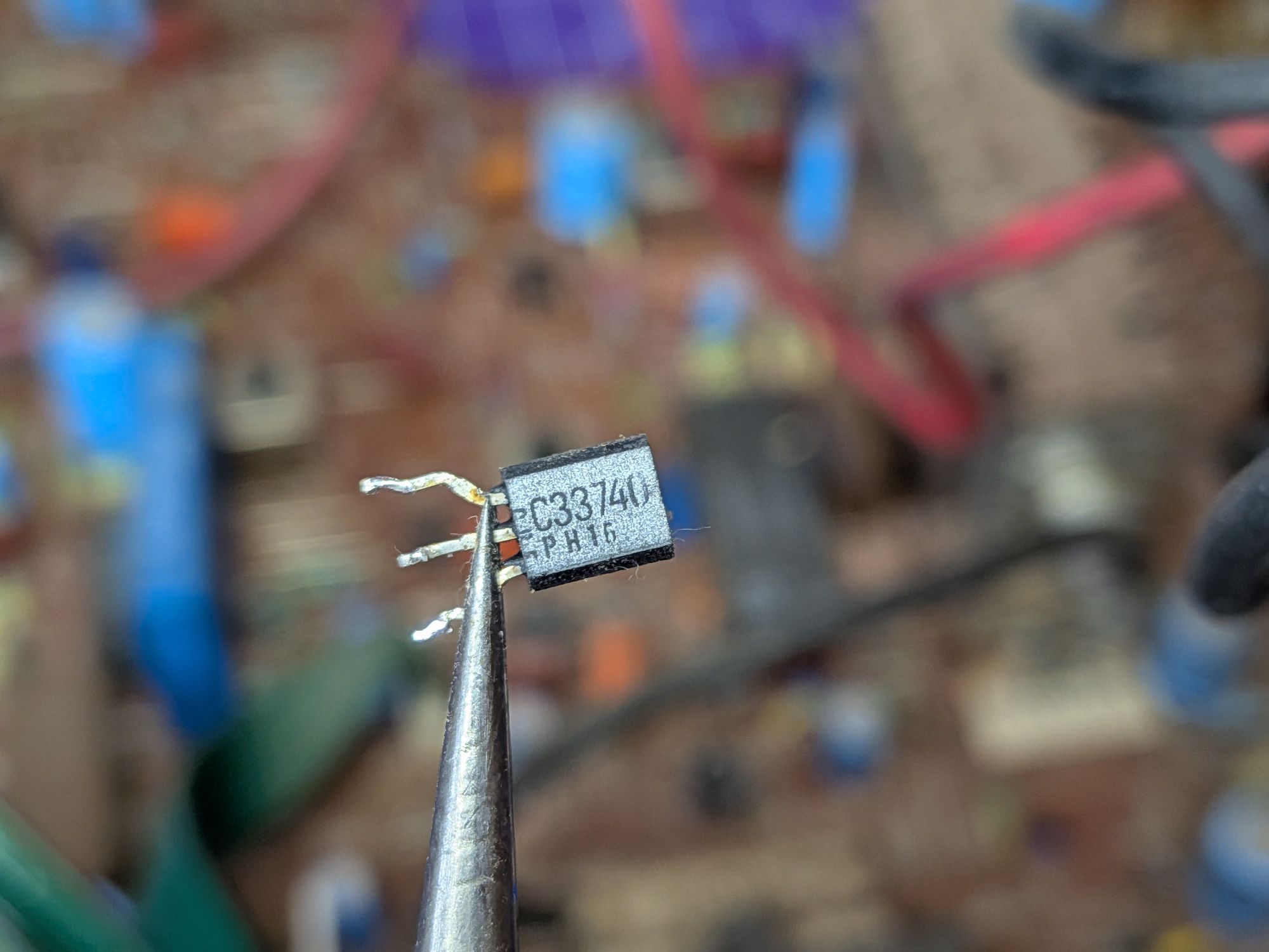
Because it switches a lot of energy, it is mounted onto the large heatsink. Seen in the later pics with the retaining clip removed. It is a C3795B, or with a google a 2SC3795B. It’s common to not mark the 2S or 2SC.
Unfortunately these are long obsolete now but I was able to find some so ordered a couple, in case it failed again in testing. They can sometimes blow again straight away, or when turning the TV off, which is a sign of failing high voltage capacitors. It’s difficult to test those, without specialised equipment, so it’s best to have a spare to hand.
While waiting for the replacements to arrive the rest of the circuit and flyback output circuits were checked for any shorts. The board has a helpful diagram of the flyback windings, which made them convenient to check, at least for continuity, lack of shorts, and sensible seeming resistance values with a multimeter.
The HOT is driven by a couple of smaller transistors and some zener diodes, which could all be tested too. There are some large resistors to check and various related components. It’s best to rule out any further faults as far as possible before applying power again
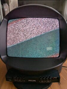
When the parts arrived it was ready for testing..
It lives!
It’s still a bit naked at this point, with the back still removed. It wasn’t left on for long but it was possible to inspect everything with a thermal camera to see whether there was anything becoming unusually hot.
A bit of research had highlighted a possible failure point as one of the chunky resistors at the back of the board. It restricts current flowing through a zener diode in the horizontal drive circuit, so was important to check.
Powered it on and off a few times to check for the high voltage capacitors failing and all seemed well with it.
As this failed when something was connected to the aerial socket, it was best to test initially without anything connected. It was left turned on, just displaying static for some time. After around 30 minutes though it turned off or died again, with no indication what had happened. There was no pop or bang and no magic smoke was released.
Unplugged immediately to prevent possible bad things from happening. After the joy of “It lives!” came the inevitable “Oh crap!” and the board had to come out again to be checked over, again.
There was nothing apparently wrong. Nothing appeared to have died or melted. It was all as it had been when first turned back on. Back to the research then. This is where we need to talk about the electrical techy stuff too.
This TV has what is known as a Hot Chassis. What that means is that rather than the ground being connected to Earth, or an isolated DC 0V, it is actually tied directly to one side of the mains electricity supply.
In the UK, that happens to be the Neutral side which, in theory at least, should be at Earth potential. It is tied to Earth at the centre tap of the transformer in the electricity substation, although the two wires are kept separate in your home. Not wishing to get too deep in the weeds.
As the chassis ground is connected to one side of the mains though, for safety anything connecting to it has to be electrically isolated from the chassis. In this case, it just has an RF input so there should be no direct connection between the aerial socket and the chassis. It can use small isolation transformers and safety capacitors so that it is *in theory* everything outside is completely isolated from everything inside.
After reassembling the TV again and plugging in, when power on the red light was on solidly and nothing on screen. After researching, the solid red light can mean it has switched into a protection mode and will refuse to turn on, which is kind of what it was doing. Nevertheless after pressing some buttons and turning it on and off a few times, it did come back to life.
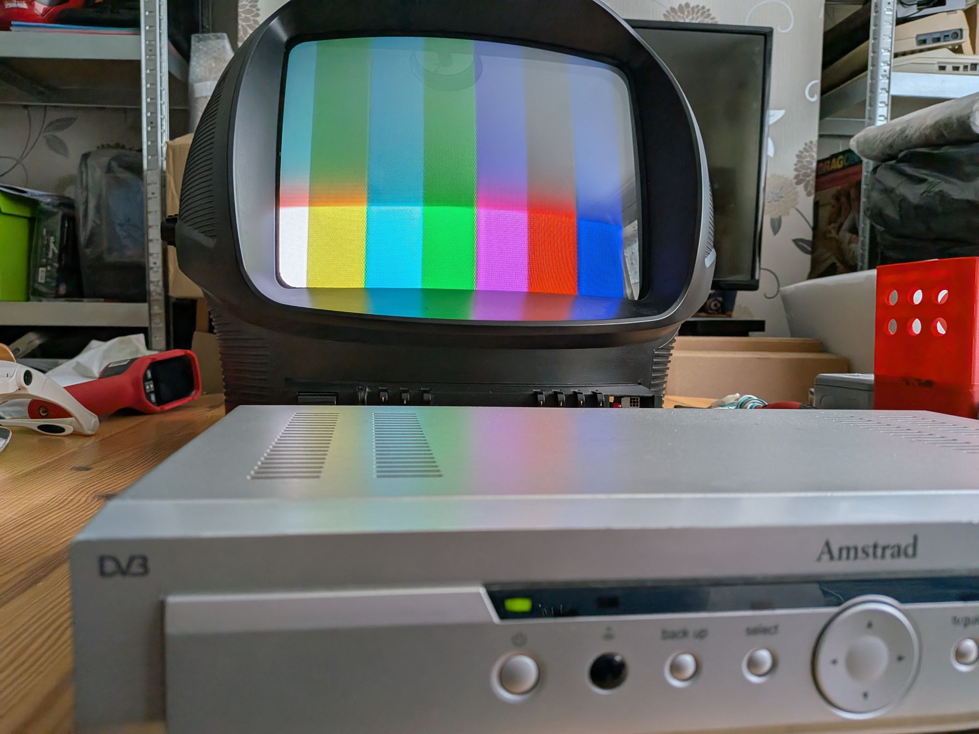
What I suspect happened was that it hadn’t failed and gone into a protection mode but had just automatically turned itself off after a long period displaying static, with no input. A power saving feature. The solid red light was just the Standby setting, waiting to be turned on with the remote. Button mashing the front panel had brought it out of standby.
With it now up and running again it was important to check on the isolation at the aerial socket, as plugging something in is what had killed it in the first place. There was no measurable resistance between either side of the socket and the chassis ground.
Measuring from either side of the aerial socket, to the actual Earth of the power socket showed it was sitting at around 6V AC. It is normal to expect to measure a small voltage here, to Earth, as it is isolated and in effect floating.
The owner had plugged in a games console, with the TV turned on. Depending on the console and it’s power supply, the shield of the RF output would likely be at Earth potential. As it was connected, it would suddenly have discharged the accumulated charge and Earthed the floating voltage present at the TV aerial socket.
To the TV this would seem like a sudden surge, which would have drawn too much current for one of the secondary circuits of the flyback and in turn the primary of the flyback and in turn the HOT, causing it to become shorted. Presumably.
With that in mind though and short immediate availability of expensive replacements and needing to test the TV for a long period with a video input, I decided not to risk connecting anything directly to the TV at this stage.
An extra level of signal isolation was needed, to avoid the same thing potentially happening again. Although, as long as everything is connected before being plugged in, it should really be OK. It was the fact it was connected with the TV turned on that had killed it.
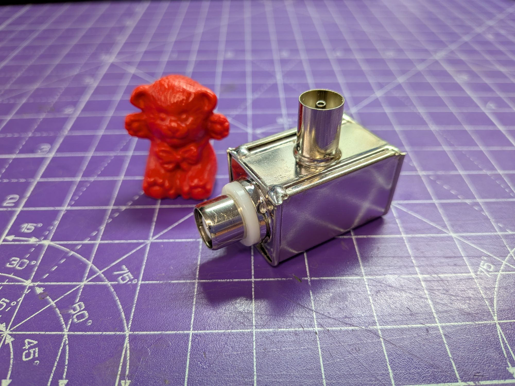
There is a doohicky you can get, though not easily, called a Galvanic Isolator, or Ground Loop Isolator. Essentially, it replicates the internal isolation, externally. Disconnecting the inputs from the outputs. It should offer protection to the TV from what is being connected and also protection to the connected equipment from the TV.